"Li'l 4x4"
by Fred Nachbaur, Dogstar Music ©2001
3: PERFORMANCE BENCHMARKS
FREQUENCY RESPONSE
Frequency response simply indicates how accurately an amplifier passes the various frequencies of
interest. It is generally considered that the audio spectrum ranges from 20 Hz to 20000 Hz (20 kHz),
so an ideal amplifier would have a flat response over this entire range. In the real world, however,
such perfectly flat response graphs are the stuff of which dreams are made.
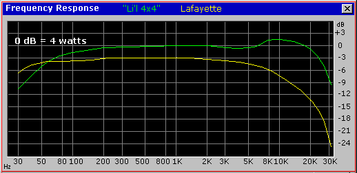
Here is a comparative plot of the frequency response of both the Li'l 4x4 (green line) and the KT-92
(yellow line). Note that 4 watts is taken as the 0 dB point, which is why the KT-92's "flat"
portion is 3 dB below the Li'l 4x4's. As such, the graph also compares relative output power.
Frequency Response comparison
Note that the KT-92's output response is down 3 dB (half-power point) at 8 kHz. This is directly
attributable to the relatively low quality output transformer. In comparison, the Li'l 4x4's high
frequency response is good up to beyond 20 kHz, after which it rapidly drops. This is entirely due
to the large amount of NFB in this design, since the transformer I used is very similar.
There is, in fact, a response hump at about 8 kHz in the Li'l 4x4's curves. Again, this is a
side-effect of high NFB containing an output transformer with high leakage inductance within its
path, and an illustration that NFB is not necessarily a panacea for all amplifier ills.
In my particular case, this hump actually works to advantage, helping to offset the drop in response
of the single 8-inch speaker I used for the instrument amplifier. However, if you should want to get
rid of this hump, you'd either have to do more tweaking of the amplifier's bandpass profile (messy),
or get a better output transformer (easier but probably costlier).
Finally, it should be noted that the Li'l 4x4's bass response looks worse than the KT-92's. In fact,
this was intentional, as discussed in the "How It Works" section, I wanted bass response to
roll off below around 80 Hz, and designed the bandpass and feedback networks accordingly.
HARMONIC DISTORTION
Harmonic Distortion measurements provide an index of an amplifier's (or other system's) linearity
characteristics. In a perfectly linear system, application of a pure sine wave at its input will
produce a pure sine wave at the same frequency at its output. However, any non-linearity will
introduce frequencies at integer multiples of the fundamental frequency. By measuring the harmonic
content of the output, with single frequency (pure sine wave) input, we can get an indication of
how accurately the system reproduces the timbres of the sounds applied to it.
We often hear the term "Total Harmonic Distortion" applied as an index of the goodness of
audio gear. While this can indeed give some indication, a much better way to analyse harmonic
distortion is by use of spectrographs that show the actual harmonic content of each component. The
graphs here were produced by generating a pure sine wave (at 1000 Hz), feeding it to the amplifier
under test, and recording the output (set to a fixed power = 1 watt = 2.83 volts RMS into an 8-ohm
resistive load). Note that this is well within both amplifiers' "comfortable" region, not
at full power. I've found that this is a better gauge of response in typical usage, with
real musical sources, than the more usual "worst-case" measurements. Ten seconds of the
resulting recordings were then analysed using an FFT analysis program, and graphed for easy
comparison. (Two-second snips of the actual recordings are available in
4x4test.zip should you wish to hear what they actually sound like.)
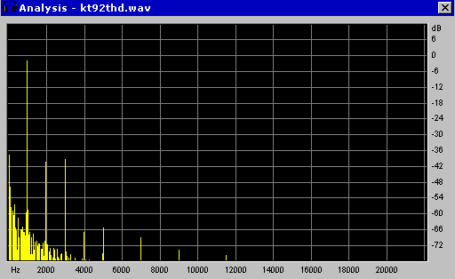
Lafayette KT-92 Harmonic Distortion
THD = 1.51% @ 1 watt
The large spike at 1000 Hz is our signal of interest. The most significant harmonics are at 2000 Hz
(2nd harmonic) at -40 dB, and 3000 Hz (3rd harmonic), at about -39 dB. The rest are way down in the
mud, really not a bad response at all! However, look at all the stuff at the low-frequency end; this
represents hum and noise content (60 Hz supply frequency at -37 dB, and its harmonics). And yes, the
KT-92 was isolated using an isolation transformer for these tests. ;-)
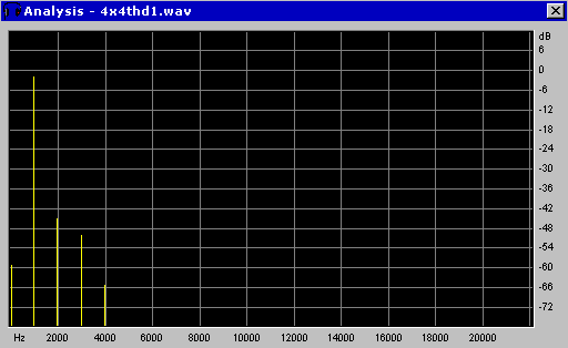
Li'l 4x4 Harmonic Distortion
THD = 0.66% @ 1 watt
Here's how the Li'l 4x4 fares under the same conditions (1 watt output, 1000 Hz test signal). Again
the most significant harmonics are the 2nd and 3rd, at -45 dB and -50 dB respectively. Harmonics
above the fourth are off the scale. But note that the 4th harmonic response is no better than the
KT-92! This graphically shows that our feedback system works very well to reduce the most significant
harmonic distortion components, but is not a magic bullet.
Where the Li'l 4x4 really shines is in the hum and noise department. This is partly because of the
improved power supply, partly because of careful layout and "star grounding" techniques,
and partly due to NFB. This little thing is quiet! The first comment I got when demonstrating it to
a fellow musician recently was "Is this thing actually turned on?"
INTERMODULATION DISTORTION
Arguably a better gauge of distortion is "Intermodulation". This measures another aspect of
non-linearity; when two different frequencies are applied to a non-linear circuit, mixing occurs and
the result will include sum- and difference- frequencies, along with their harmonics, in addition to
the two original signal frequencies.
Sonically, intermodulation typically is perceived as "muddiness" or "lack of
definition" as frequencies get smooshed together. More severe cases of intermodulation result in
identifiable, audible artifacts (sounds that aren't in the original source).
The IMD tests were done using equal amplitudes of 100 Hz and 3000 Hz signals summed together. The
peak amplitude was set to be the same as the constant-frequency 1-watt point (note that the actual
total power is therefore somewhat less than 1 watt). In other words, we're again being
"kind" in our analysis, taking our measurements at a typical operating level rather than
at the worst-case scenario, the full-power point.
Here's the Intermodulation graph of the Lafayette KT-92:
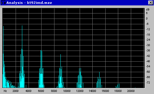
KT-92 Intermodulation at 1 watt, 100/3000 Hz
The two tall peaks represent the source signals of 100 Hz and 3000 Hz. Note how each harmonic of
3000 Hz is straddled by multiple mixing products of 100 Hz. While, again, this response certainly
is not horrid by any means, we can probably do a bit better. Here's the Intermodulation profile for
the "Li'l 4x4" under the same conditions. In comparison with the KT-92, this particular
little picture is worth a thousand words...
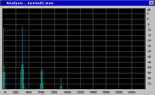
Li'l 4x4 Intermodulation at 1 watt, 100/3000 Hz
OVERDRIVE RESPONSE
Finally, let's compare how the two amplifiers behave when given an input signal with 50% overdrive
(in other words, a signal 50% above that required for maximum un-clipped output power). First, here's
how the KT-92 looks when overdriven:
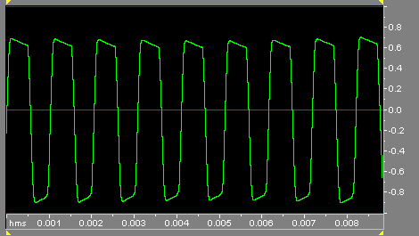
KT-92 Overdrive Distortion
Note that the flat-tops are relatively smooth, a sign of the "soft" clipping so valued by
tube guitar-amp owners. Note also that the tops and bottoms aren't symmetrical. Even though I had
adjusted the phase inverter to provide equal drive to both 35C5 grids, there is still assymetry
during overdrive due to parametric differences between the two tubes. (Generally, this would not be
considered a problem, but I thought I'd explain it in case anyone should wonder.)
... and here's the "Li'l 4x4" under the same overdrive conditions:
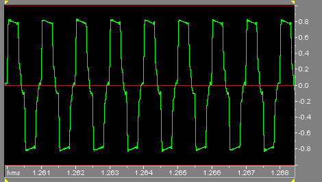
Li'l 4x4 Overdrive Distortion
Not only are the edges of the clipped tops very hard, they also contain high-frequency artifacts as
the NFB system loses its grip. What's more, crossover distortion due to the Class AB operation become
extremely pronounced, and even sports additional artifacts. In other words, the signal has gone to hell
in a handbasket.
The sound is a particularly dirty species of overdrive distortion, quite reminiscent of the sound
of the Mesa Boogie amplifiers when they're overdriven. (Yes, the Mesa Boogie uses a high degree of
negative feedback around a high gain amplifier block.) It's actually rather interesting to listen to
the sound as a chord is played; from very dirty, the signal abruptly gets sparkling clean as it drops
below the clipping level and the NFB system starts working again.
So there's another trade-off. If you're looking for a guitar amplifier with controllable overdrive
characteristics, this one isn't it. But if you play "clean", you won't find many low-cost,
low-power designs that will even hold a candle to it.


