
| McTube User Feedback |
|
These pages document users' feedback
and experiences using "The Real McTube". If you have any suggestions, mods,
component changes or other feedback, please email me at
fnachbaur@netscape.net for inclusion on this page. |
|
Now available: Sound samples! If you have any sound bites of your usage of "The Real McTube", let me know. This is page 1. More recent entries may be found on Page 2. |
|
Important: A couple users have written, saying that the tube didn't even light up. In both cases it was due to counting the tube pins in the wrong direction. If you're unsure about which way the tube numbering goes, click here. (Use your browser's Back button to return to this page afterwards.) |
|
The B+ increase [to 270V] made it a little less distorted. I was thinking of using in in an FX in/out loop where increased headroom might be a help. At the moment it's 100k/1.5k/5uF on both stages in imitation of a Dumble overdrive stage (which had 300V B+). However, it does work well connected to the input of a tube amp, the "Volume" control then becomes a "Master Volume" for the 2 McTube stages plus the input stage of the amp. I was going to have use the centre tap of the second transformer to voltage double, so I could switch from 120VAC to 240VAC. I might end up doing that. It's in a metal fax/modem box with just 2 knobs and 2 sockets. Plenty of room for another tube. I have to remember to ground one of the cathodes to drain the (2x330uF) caps every time I open it up, I have to force myself to remember it's not really a stompbox with 270VDC. -- Frank Clarke 27/02/2001 |
|
It's interesting to see you used 2 12vac trannies for this one. I just built a version using two Radio Shack 12vct trannies....grounded the ct and pin 9 of the heater....then fed the 6vac legs to pins 4 & 5....quiet as a pin and no extra parts. I've been building them in old external harddrive cases (the heavy metal kind...2" x 9" x 9"). They give tons of space..are generally free for the asking...and have grounded power connections already in place. I've been using the 90 degree tube mounts from Antique Electronic Supply (fairly inexpensive) and have been thinking about using one of National Semiconductor's 12v power amp chips inside for a complete practice amp project. Sorry so long-winded.... anyway.... thanks for creating such a cool project! I love the one I just built for myself (used .1 & .068 values for Rk) and it works fantastic for my Martin Thinline pickup in my Alvarez Yairi acoustic. :) -- Brad Myers 28/02/2001 |
|
I would think you could use [2] 12v ac types @500 ma wall warts, and add the other stuff for the power supply, since these are probably not centertapped, I would think. What do you think about this? -- Doug George 20/03/2001 Hi Doug, Yup, that would work fine. In fact, you could use the first one as-is (actually plug it into the wall! Fancy that!) and use the second one inside the case as a step-up transformer. Mind if I add your suggestion to my "Feedback" page? -- FN Sure, use my suggestion. Parts Express in Dayton, Ohio has on sale right now: 12v ac @ 500ma for $1.99ea. p/n 129-310. Web site is www.partsexpress.com. |
|
Using the Real McTube II with 230VAC Several people have inquired about how the circuit should be modified for use with 230 Volt AC, as is used in many parts of the world. One was also concerned about the difference in power line frequency (50 Hz instead of 60 Hz). Addressing the second point first, the slightly lower frequency does not have a significant effect on the design. If you like, you can increase the value of the filter capacitors in the power supply to the next higher available value. However, this isn't really necessary, since enough leeway was built into the design to accomodate the lower frequency. Regarding voltage: for 230 volt operation, the step-down transformer must be a suitable 230 --> 12 volt unit, at 500 milliamps. However, do not use an identical transformer as the step-up transformer T2; otherwise you'll have twice the B+ that the circuit calls for. This circuit was intentionally designed to run on a somewhat lower than usual B+ (mildly "starved" operation) in order to facilitate going into overdrive; a higher B+ would defeat this purpose, and would also require adjustment of the plate and cathode resistors. For the second transformer you can either use a 115 --> 12 volt unit as specified, or use a 230 --> 24 volt at 200 milliamp transformer. Either option will give the proper 140 VDC or thereabouts for proper operation. |
|
Minimum Size for T2 I'm finally going to build the Real McTube 2. It looks great! However, I have a question: I want to fit this in as small a housing box as possible, so what is the minimum value (VA or mA) for the SECOND transformer. -- Oskar Bruil 05/05/2001 The actual current consumption from T2 is less than a milliamp, so the actual required VA rating is very low. However, with very small transformers (less than around 1 VA, equivalent to about 100 mA at 12 volts), you might find that you won't quite get the expected 140 volts DC or thereabouts. The reason has to do with losses due to wire resistance as well as magnetic losses in the small core. If you have a likely candidate, you can certainly try it out. Wire up the power supply portion first, before firmly mounting the transformer(s), and use a 220K, 1/2 watt resistor as a dummy load. If you have no less than about 130 volts DC, and if the little transformer does not heat up excessively after about 1/2 hour of operation, it should be just fine. -- FN |
|
Tone Controls for The Real McTube Look at the picture that's the control, which I use for the Real McTube, I put it in between R8 and RV2/R9 of the circuit. But doing this decreased the maximum output. You've already mentioned in an other email that I should make a smaller voltage divider. How should I do it in my situation with the tone control in between of the divider? Which resistor value should be increased or decreased? -- Thomas Poms 04/05/2001 Ah, I see. This is a pretty straight-forward passive tone control, all you need to do is replace R8 with your circuit. (Point marked In goes to C8, point marked Out goes to RV2.) Remove R9 entirely. That should do the job for you. -- FN 05/05/2001 That's it, now I have enough volume to get my full power out of my powerstage. This tone control is really cool, sounds great in combination with the Real McTube II. Thanks, Tom -- Thomas Poms 05/05/2001 |
|
Dual McTubes? I've received a couple inquiries about getting even more gain by using two Real McTube circuits together. This is certainly possible, and is one way of "pushing the envelope" as regards tube overdrive. All you would have to do is to connect your instrument to the input of the first, whose output connects to the input of the second McTube, which in turn drives your main amplifiers. There's no reason why you couldn't power them both from the same power supply. T1's rating should be correspondingly higher (12 volts at 800 mA should suffice), but T2 should be alright as specified. Simply wire all the filaments in parallel. For the B+ portion I would recommend significantly increasing the filter capacitor values (to, say, 100 microfards) to reduce the possibility of oscillation. It would also be a good idea to shield the stages from each other. The best approach would be to build two separate, independant units. This also give the best flexibility, you can use them in cascade for super-high gain, or use them in stereo (for instance, connect your bridge pickup to one channel and your neck pickup to the other) or anything else your imagination might conjure up. -- FN 08/05/2001 |
|
More mods -- and new sound samples Jeff Leites writes, "Fred - "I finally assembled my McTube II... well, not completely, it's just on a couple of circuit boards laying on the floor, but I thought I'd record some sound samples for you. "I made a couple of small mods. I put a 220 ohm resistor between the gain pot and ground to eliminate the dead spot when the gain is completely turned down, and I put a 100K resistor from the wiper of the gain control to the un-grounded terminal. This seems to spread the gain our more. "I want to add the tone controls also. "These samples were played using my Carvin Bolt guitar, using the neck and tail pickups, both in humbucker mode. The amp is a 1965 Epiphone tube amp (more info on my pickups and amp are available at my web site). "There are 4 sound samples, clean, low gain, medium gain (though without knobs, I don't know exactly how close to medium it is), and maximum gain. "Thanks for the project - Jeff" |
|
Hissing McTube - and yet another sample Pedro in Portugal wrote a few times about his implementation of The Real McTube, reporting a strong hissing sound. We (correctly) diagnosed the problem as an oscillation, there was something about his particular layout that caused the instability. What finally solved it was installing a shield around the tube. So if you're having similar difficulties, perhaps this will solve the problem for you also. Pedro has also documented his implementation, including his mod for use with 240VAC, at his website (under Effects --> McTube 2). -- FN He writes further, "I then tried the 12AT7 (I got alot of those!) and sweet music from heaven! Really smooth fuzz. And the 12AT7 doesn't need grounded shield. No hiss at all. For more distortion I used an LPB1 before INPUT. As for the sound sample, I used my PC's soundcard LINE INPUT for recording and later was told not to do so, I needed to use a mic. placed close to my amp or I could effectivly burn my soundcard! (ouch!) Also, that sample was done with a bridge humbucker, with McTube at full Gain." |
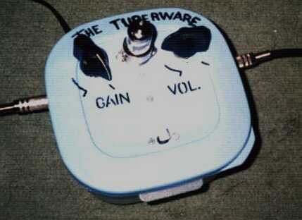 Pedro's "Tuberware" Real McTube II |
|
Brad's McTube Saga Brad Davis wrote a few times, and sent along a novel sound sample demonstrating his McTube with two guitars, multitracked using Cakewalk. Brad ran into an interesting situation, in that everything was fine spread out across the floor, but the circuit "squealed like a pig" when finally encased. After having him try a few things, the problem ended up being related to component layout around the socket. Moral: Keep your wiring between the two stages physically separated as much as possible, while keeping wire runs as short as practical. Such layout-related problems can often be isolated by (carefully!) moving components and wires with the unit on, using an insulated prod. A picture of Brad's finished stompbox is shown below. |
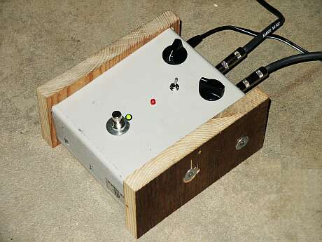 Brad's Real McTube II implementation |
|
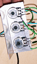
The Real McTube in Italy Sergio built up a beautifully laid-out implementation for 240v power, creating it in three separate modules: power supply, main amplifier, and tone stack. Photos of the modules are shown below: 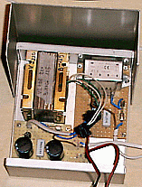
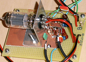
|
 Reducing Hum - and some comments Reducing Hum - and some comments
Sylvie writes, "Hello genius boy, I finally understood my mistakes for this project. The second filtration for the filament is very important to eliminate the hum...We must absolutely do that to have a good sound!! There is another problem... the 12.6V transformers. We must get out them of the box because they produce HUM... It is a good isolation for the noise...You should mention that in your article. The sound of the real Mctube is AMAZING! It's like the old stuff... Beatles, Alice Cooper, CCR!!!! It's perfect for cheap peavy amp... Just put on and wait a bit to light the filament and you're ready!! Thank you!!! ** Your project looks like a part of the amplifier 'twin reverb' of Fender! ByeBye!! |
 240V McTube Revisited 240V McTube Revisited
Duncan Eliot writes (21 August 2002), "Thanks for introducing me to the wonderful world of tubes. Just a quick note on 240v operation after reading your feed back section. I found the simplest solution was to use a set 12.6V CT trannies. 240v into T1 with heaters running off the 12v side and then just feed 6.3 volts using the CT back into the second trannie. "On this note could a switch be implemented to change between 6.3 and 12.6 (ie 120 -> 240 on the B+). What effect would this have and would mods be necessary?" -- Duncan Eliot Running a higher B+ would sort of defeat the original purpose of the device, but might be useful if you wanted a cleaner preamp (such as for mics, or maybe acoustic guitar pickups). You probably wouldn't need to change any other values, except perhaps increasing the value of the cathode resistors. -- FN |
