
Written Sept. 2002
1st Rev. Oct. 2002
2nd Rev. Nov. 2002
3nd Rev. Dec. 2002
EXPERIMENTS WITH PARAPHASE SPLITTERS
(A Vacuum Tube "Multimedia" Amplifier)
by Fred Nachbaur, Dogstar Music ©2002
1: INTRODUCTION
It's been said that "Necessity is the mother of invention." This could be extended to,
"New tube circuits depend on the tubes you have on hand." In my case, it seems that I've
accumulated an inordinate number of 6X8 and 6X8A triode-pentode hybrid tubes; although this device is
similar to the common 6U8 and 7199 tubes commonly used in audio circuits, the 6X8 has the disadvantage
of having both cathodes internally tied together. Perhaps that's why I ended up with so many of them;
no-one else could figure out what to do with them either!
I therefore set out to find an application. The target project was a small stereo amplifier for a
friend and fellow musician's computer system. I had an ideal enclosure, decided on a simple 6AQ5-based
push-pull topology, and found some output transformers from a fellow enthusiast on rec.audio.tubes.
I had exactly six tube socket positions available; therefore, the preamp and phase splitting functions
had to be accomplished using a single tube for each channel.
With a 6U8 or similar tube, the pentode portion could be used as a preamplifier, and the triode as a
cathodyne ("concertina")
phase splitter. However, the 6X8 with its pesky common cathode precludes such a circuit. Time for
some experimenting.
2: BACKGROUND
Push-pull output stages require two separate input signals, of approximately equal amplitude but
opposite phase. In other words, as the one signal is increasing (becoming more positive), the other
one must decrease (become more negative). The out-of-phase signal is therefore simply an inversion,
or mirror-image, of the in-phase signal.
Let's have a look at one of the oldest phase splitter designs, a simple amplifier circuit with a
rather fancy name: the "Paraphase". This is really nothing more than a low-gain
common-cathode amplifier stage; the fancy name comes about from its function, rather than any
circuit details per se. The schematic below shows a workable paraphase using the venerable 12AX7
twin triode:
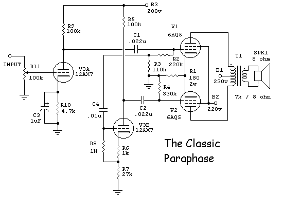
The Classic Paraphase Circuit
The in-phase signal is applied from the plate of the preamplifier, V1A, to the grid of the top
output tube, via coupling capacitor C1. The grid resistor to this output tube is split into two
sections, R2 and R3, forming a voltage divider (3:1 with the values shown in the schematic). This
divided-down voltage is applied to the grid of the paraphase stage, V1B. This stage gets its grid
bias from a portion of the cathode resistor, R6.
The AC plate load of the paraphase stage essentially consists of the parallel combination of the
plate load resistor R5 (100k as shown here), and the grid resistance of the lower output stage R4
(330k), or about 77k. Note that this is approximately 3 times the value of the cathode resistor R7
(27k). Under the assumption that open-loop stage gain is quite large, and that therefore cathode
voltage will approximately equal applied grid voltage, it follows that the voltage on the plate will
be about 3 times the grid voltage, or about the same level as the voltage on the plate of the
preamplifier but with the opposite phase.
An example of a commercial design using the classic paraphase is the
Lafayette circuit used as the starting point for the
"Li'l 4x4" project.
3: A CATHODE-COUPLED PARAPHASE
Now let's build a paraphase by using a grounded-grid topology instead of common cathode. The input
to the phase inverter is applied at the cathode, allowing us to use the 6X8 with its internally
joined cathode connections.
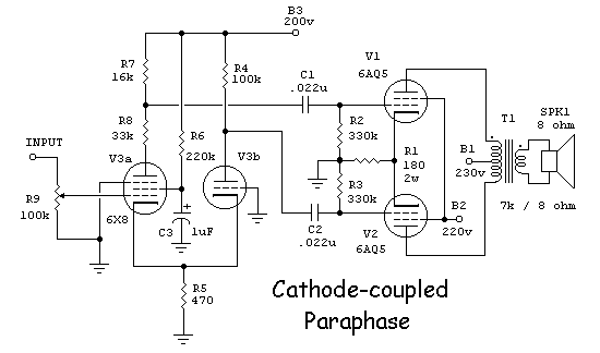
The Cathode-Coupled Paraphase Circuit
As before, the in-phase signal appears at the plate of the preamplifier stage (the pentode section
of the 6X8) and is applied to the grid of the top output tube. However, unlike the classic design,
a shared cathode resistor provides the coupling between the preamplifier and the phase inverter
(the triode section of the 6X8).
Note, however, that the inverted output signal at the plate of the triode will be of considerably
less amplitude than the in-phase signal. With the 6X8 and the component values shown, this will be
about 1/3; this is why the plate load of the pentode preamplifier stage is split into two sections,
giving a 3:1 attenuation of the in-phase signal in order to match to the amplitude of the inverted
signal.
Note also that the shared cathode resistor introduces some local feedback to the pentode stage, so
overall gain is only about 10 (20 dBv). Still, this is enough gain for many applications; in the
circuit shown, only about 0.7 volts RMS is required for full output. Given that today's sound cards
can output up to several volts from the line output, it would certainly be adequate.
The circuit also has a certain simple elegance; the entire preamp and phase splitter section consists
of only five resistors and three capacitors (the two coupling caps and a screen bypass). If desired,
part of the plate load of the pentode preamplifier stage can be made adjustable, such that AC balance
can be adjusted exactly (perhaps by adjusting for zero AC voltage on the shared cathode resistor of
the output stage).
4: THE "ENHANCED" CATHODE-COUPLED PARAPHASE
For the target application, it was deemed desirable to have additional gain in order to offset the
insertion loss (about 10 dB) of a simple "Big Muff" style of single-pot tone control, to
give the end user some degree of control over frequency response. So the Cathode-coupled paraphase
was modified slightly, as shown in the schematic below:
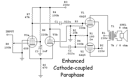
The "Enhanced" Cathode-Coupled Paraphase Circuit
All we've done here is to sample part of the in-phase output signal at the grid of the top
output tube, and applied it to the grid of the paraphase stage. Most of the coupling is still
via the cathode as before, but by sampling a very small portion (about 1:33) of the in-phase signal,
the gain of the paraphase is increased by over 10 dB.
There are a few interesting aspects to this modified circuit:
-
The parts count is exactly the same as the pure cathode-coupled circuit described earlier.
-
The final topology begins to resembles the classic paraphase, but does not require the additional
coupling capacitor
-
The gain of the pentode stage is actually increased also. To understand why, consider first what
happens when a signal is applied to the grid of the pentode. An increasing (more positive) grid voltage
causes an increase in plate current, and therefore an increase in current through the common cathode
resistor. This represents a negative feedback term, since it will tend to decrease the
grid-to-cathode voltage.
Now consider what happens when we inject part of the in-phase output signal into the grid of the
paraphase. This will be out-of-phase with the input signal, and will therefore cause a decrease
in shared cathode current. It therefore opposes the negative feedback element, and actually represents
a positive feedback term. In fact, if the injection ratio is made too high, the circuit will actually
oscillate!
-
Given that there's no such thing as a free lunch, what's the cost? The answer - increased harmonic
distortion, since we've essentially cancelled out the negative feedback formerly introduced by the
shared cathode resistor. Essentially, we've restored performance to be virtually identical to the
classic topology originally considered; the difference is that we've met the design goal of being
able to use tubes with shared cathodes. At the same time, we retained a relatively high gain of about
40 (32 dB) per phase, or 80 (38 dB) plate-to-plate.
A similar approach could be used for dual triodes with shared cathodes, such as the common 6J6. I'll
leave it to you to work out the details.
A more rigorous analysis of the circuits presented here, along with measured harmonic distortion
behaviour, may follow at a later date.
5: THE FINAL AMPLIFIER CIRCUIT
Here's the complete schematic of the little tube multimedia amplifier, fleshed out with the power
supply and input tone-control circuitry. Again, the parts on hand dictated the power supply topology;
the relatively high power transformer voltage dictated the choke-input filter. (Even though the
presence of C9 makes it look like a capacitor-input filter, its low value makes it have a neglible
effect on output voltage. It was added as a tweak to help reduce 60 Hz. harmonics.)
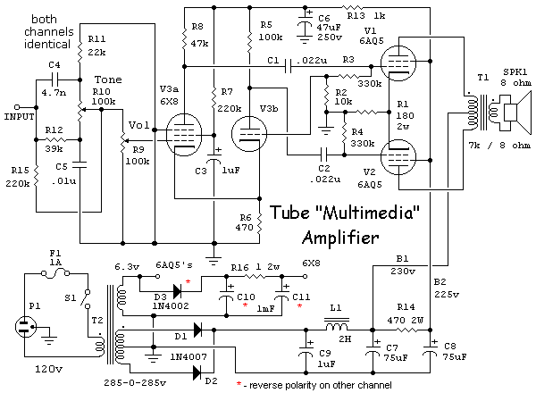
The Final "Multimedia" Amplifier
How does it sound? In two words, Just Ducky. The amplifier has the warm, gutsy sound characteristic of
tube amplifiers with little or no global feedback. The tone control circuit puts a mild dip in the
midrange, which tends to enhance that warmth - especially when used with efficient speakers such as
the old theatre speakers that the end user plans on using with the amplifier.
6: ANOTHER APPLICATION
For the Marantz retrofit project I expanded this
paraphase idea a bit further. The circuit shown below sports the following refinements:
-
An additional -50v negative "B" supply increases the headroom of the grid-enhanced,
cathode-coupled paraphase splitter, to cater to the somewhat higher drive requirement of the
TT15 output valves.
-
Much lower plate load resistors are used, to help swamp the difference in plate resistance, and
provide a more equal output resistance to the two push-pull grids.
-
The lower value of shared cathode resistor biases both sections somewhat "hotter",
placing them into a more linear region of operation.
-
About 6 dB of global feedback from the speaker output, to the main amplifier input, provides
further clean-up of distortion products, and significantly lowers the output resistance of the
amplifier, for a smoother frequency response independant of speaker parameters. Note, however, that
this approach assumes a fixed input impedance (approximately 5k in this case). This is
not always a given, so you'll have to be careful if you plan on using this feedback
method.
-
The amount of signal applied to the grid of the paraphase splitter is adjustable using a trim-pot.
A good way of setting this is to monitor the voltage on the 10-ohm sensing resistor on the output
tube shared cathodes, and adjust the trimmer for minimum signal. Interestingly, the residual signal
under these conditions is predominantly 2nd harmonic (twice the source frequency). See the
spectrogram and discussion that follows.
Changes as of December, 2002:
The circuit as published originally ended up being somewhat unstable, taking out the 10-ohm
cathode protection resistors apparently at whim. As near as I can tell, the amplifier would
break into ultrasonic oscillation under certain conditions. The following changes stabilized
it:
- Changed shared cathode resistor to 100 ohms, to give about 7 volts of cathode biasing in
addition to the fixed grid bias.
- Added 1k grid-stopper resistors to the TT15 finals.
- Increased final screen-stoppers from 100 ohms to 470 ohms.
- Decreased grid resistors from 330k to 220k.
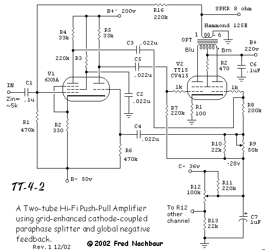
The Improved GE/CC Paraphase
Here is the power supply for the amplifier. Note how the voltage quadrupler circuit allows the
use of the original power transformer designed for the solid-state amplifier that this circuit
replaces. The winding that formerly serviced the preamp/ tuner sections now provides the low-current
negative "B" supply for the preamp tubes, and the bias for the output tubes.
An added transformer salvaged from another old solid-state stereo provides the low-voltage DC for
the pilot lamps and the preamp tube filaments, allowing the original low-voltage line to be
reserved for the TT15 filaments. Another winding on this added transformer powers the tone-control
preamps and tuner section of the receiver, further reducing the demand on the original transformer.
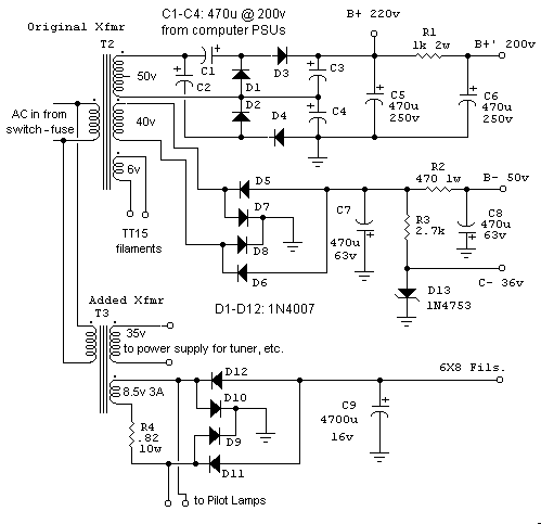
Power Supply
As mentioned earlier, this circuit shows a noticeable amount of 2nd harmonic content in the
shared output tube cathode current. Since this represents a common-mode term, most of it will
be cancelled out in the output transformer. However, it's interesting to note that a spectrogram
shows this circuit's response to be a bit atypical for push-pull amplifiers.
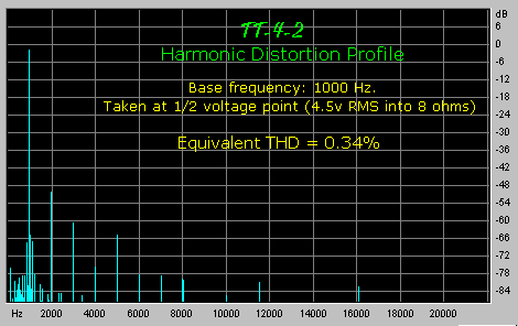
Harmonic Distortion
This plot was taken at the 1/2 voltage point (1/4 power), which I've deemed to be fairly
representative of where the amplifier will be operating most of the time. Note that while the THD
figure of 0.34% is quite good for such a simple circuit, the unusual thing is that the most
significant term is the second harmonic, at approximately -50 dB.
It's therefore no surprise that the amplifier has a sonic "signature" very much like a
good single-ended design. I can only surmise that this is due to the inherently un-symmetrical
nature of this phase-splitter, combined perhaps with slight differences in transconductance between
the two valve sections. Better matching between sections and perhaps real-time distortion monitoring
whilst adjusting the symmetry pot would probably reduce this even further.
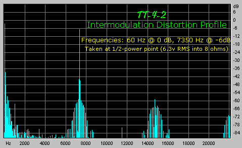
Intermodulation Distortion
Here is a plot of intermodulation distortion, using a test signal of 60 Hz. at 0 dB, combined with
7350 Hz. at -6 dB., and gain set such that the total of both components produced 5 watts at the
output (1/2 of maximum power). No big surprises here, the highest IMD product is at a reasonable
-40 dB. This is about 6 dB better than the otherwise similar "Li'l 4x4", which sports
about the same amount of global negative feedback. The improvement is probably partly due to the
better output transformers, and partly because of more linear output tubes.


