A HIGH PRECISION TUBE PHONO PREAMPLIFIER
by Fred Nachbaur, Dogstar Music ©1998, 2001

4: CONSTRUCTION HINTS


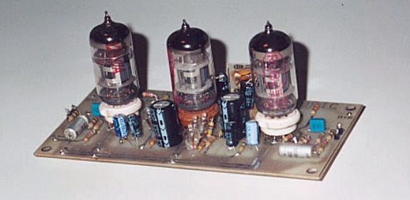
The first prototype of the phono preamp was built into a small metal box chassis, using PCB construction. I subsequently re-used the PCB module for use as one of the preamps in my RA-100 integrated amplifier.

If you wish to duplicate the layout of the PCB-based prototype, download the file sapart.zip, (be sure to read "artwork.txt" included in the zipfile) which contains the images necessary to create your PC board. Write me if you want the original Gerber files, should you have access to a "one of" PCB manufacturer. Note that the preamplifier module is designed for double-sided boards. This can be tricky, and is recommended only for experienced PC prototypers.

Note also: There is a polarized component shown on either side of the centre tube (12AT7) which is not used in normal applications; this was left as an option should someone wish to use the preamp in a "cathodyne" configuration. This, and its associated output connection pads are ignored in this design.

First prototype


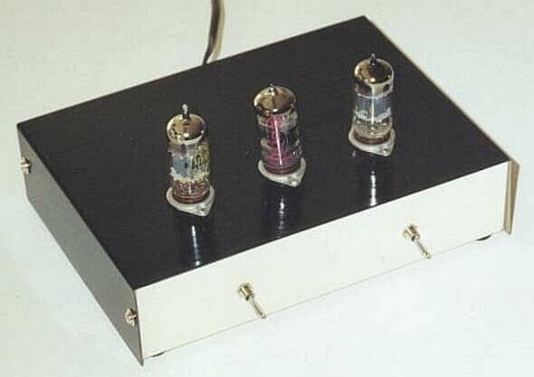
The second prototype (pictured below) used the same type and size (210 mm x 155 mm x 50 mm) steel box chassis. However, for the purpose of this article (and to assure myself that the design does indeed give good results using conventional wiring) this version was built using point-to-point wiring techniques, employing the tube socket pins and rows of terminal strips to provide the required connection points.

Testing showed no measurable (or audible) difference in the two design approaches, so use whichever technique you're more comfortable with.

Second prototype


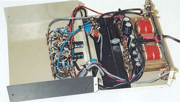
This second prototype was constructed with the bulk of the preamp circuitry on the top case-half, and the power supply, mode switching, input/output jacks, and feedback networks in the bottom case-half. If I had it all to do over, I'd leave myself more room in the top section for the many resistors and capacitors, and also more room in the bottom for the feedback networks. However, since it's unlikely that I'll build yet another of these in the foreseeable future, I leave it to you to come up with a superior mechanical layout. ;-)

The Inner Workings
The Inner Workings of the second prototype.
Note the shielded cables on all audio lines, and twisted pairs on power wires.


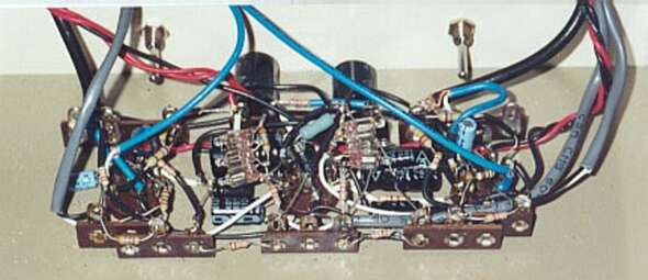
Preamp section (top half)
The top case-half, showing most of the preamp wiring.
You'll probably want to leave yourself more room by increasing the spacing
between tube sockets, and mounting more terminal strips.


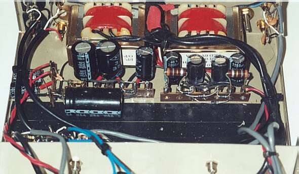
Power Supply (lower half)
The power supply section (lower case-half). High-voltage supply
on the left, DC filament supply on the right. Feedback network components
wired near the mode switch on the left side of the front panel.


Wiring tips

Other tips

Adjustment and testing

Assuming that everything goes well, there is not much to adjust. Turn the unit on and let it warm up for at least a minute. Measure the voltages at the following points (relative to chassis ground). A deviation of about 10% is nothing to worry about, but larger differences should be investigated. Compare the readings for both channels; they should agree quite well:

Plate V1A (bottom of R106/R206) 190-210 V
Plate V1B (bottom of R107/R207) 270-290 V
Cathodes V1 (top of R104/R204) 26-32 V
Grid supply V1A (top of C102/C202) 1.5 V less than cathodes
Grid supply V1B (ACG) 2V less than cathodes
Grid V2 (R115/R215) same as Plate V1A
Cathode V2 (top of R108/R208) 1.5V higher than Grid V2
Plate V2 (OUT) 290-310 V
+IN (top of R101/R201), Outputs 0V
Filaments +6.3 V (pins 4), =6.3V (pins 5)


OK so far? Congratulations! Your DC servo loops are working just great. If not, don't fret. Remember that any problem in the DC loop will probably cause all voltages to be wonky, so it may not be easy to troubleshoot. Take your time, go over all your connections, verify parts, etc. Still having trouble with one channel? Swap 12AX7A's. If the problem follows the tube, you've got a bad one. If the problem stays with the same channel, there's a problem on the board circuitry. There, you got it? Well done!

Ideally, final testing should be done using a sine-wave signal generator and oscilloscope, to verify that your performance is similar to the curves shown in the "How It Works" section. If this kind of test gear is not available to you, you'll have to use the "plug it in and see if it works" approach. Do be careful, when connecting to your amplifier, to bring the amp's volume control up from zero very gradually, in case you have a problem such as excessive hum or oscillation.

Using the preamp is pretty straightforward; connect your phono (Ceramic or Magnetic cartridge) to the appropriate input jacks, and connect the output jacks to your amplifier. And away you go!


Back Home Next
BACK INDEX NEXT