"Li'l 4x4"
by Fred Nachbaur, Dogstar Music ©2001
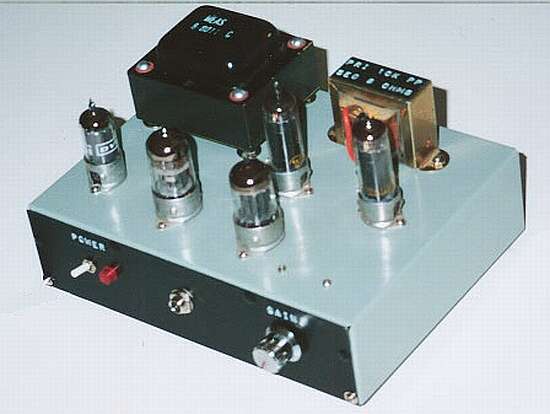
The completed "Li'l 4x4" chassis
4: Construction
COMPONENT SELECTION OPTIONS
A: Output Tubes
This project was designed with the 30A5/HL94 in mind. This tube is generally considered
interchangeable with the 35C5, and in most circuits drop-in replacement between the two types is
indeed possible. However, I do find that the 30A5/HL94 offers a somewhat cleaner sound, and
recommend using this one if you have access to it. A cursory search turned up several suppliers
that stock this tube, at very reasonable prices.
Failing that, I'd suggest the 35C5. The bias point will be somewhat different; not a problem,
the power supply as shown has a pretty wide adjustment range and you should have no problem
setting the bias pots such that you get the required 20 milliamps of cathode current (0.200 volts
on each of the 10 ohm cathode resistors).
If you're a dyed-in-the-wool experimenter, you might want to play around with either the 25C5 or
the 50C5. You might be able to squeeze a bit more power out of these, but will probably have to
raise the B+ supply to about 230 volts. Since these also appear to have a bit more gain, you may
also need to increase the values of C12 and C13 slightly to prevent oscillation. I tried the
circuit using 25C5's, and they do work in the circuit as shown; however, I wasn't too happy with
them, and am content to stick with a cleaner sound even at the expense of a bit of power.
Depending on which device you use, you will have to adjust the components in the filament supply
(R1 and D1) to suit. The table below summarises the options. Note that all types use the inline
diode except 50C5 (replace with short circuit).
| Tube type: | R1 | D1 |
| 30A5/HL94 | 33 @ 5w | Yes |
| 35C5 | 0 (short) | Yes |
| 25C5 | 33 @ 5W | Yes |
| 50C5 | 39 @ 10W | No |
B: Power Transformer
The little power transformer you see in the photos was scrounged from an old piece of test
equipment. This particular one had a total of seven windings, which I series-connected as required
for the needed output voltages.
You might similarly get lucky and find something you can use in your junk box ..er.. I mean
treasure chest. If not, the Hammond Model 269BX
should work admirably. This is the unit for which I drew up the
schematic diagram.
For 240 VAC operation, use the new
Model 369BX instead. This is identical to
the 269BX except that it has a dual primary, allowing series connection for 240 volts. You will
also have to make arrangements for the filament supply for the output tubes. If you're using a
30A5/HL94, a good option would be to use a 24 VAC at 0.5 A transformer, followed by a solid
state full-wave bridge rectifier module, and a 4700 µF at 50 volt filter capacitor. This
should provide a DC voltage suitable for the two filaments, wired in parallel. The same
arrangement should be adequate for the 35C5, these tubes were designed to be quite forgiving
about filament voltage. For 25C5 you can use the raw 24 VAC directly. 50C5's are not recommended
for this use, but if you insist get a 48 VAC at 0.5 A transformer to power these filament-power
hogs.
C: Output Transformer
The output transformer for the prototype was similarly "scrounged" from the physical
archives. This particular one was intended as a universal replacement for single-ended designs,
and had primary taps at 1.25k, 2.5k, 5k and 10k (full winding). Remembering that impedance is
proportional to the square of the turns ratio, it wasn't a great leap of the intellect to
realise that the 2.5k tap is indeed the center-tap of the winding. Similarly, the secondary was
rated for 8 ohms, exactly right for the speaker I had in mind. What luck!
You might get lucky also, and find a similar suitable transformer either in your archives or at
one of the surplus sites. The requirements are:
- Center-tapped Primary
- Primary impedance in the vicinity of 10k (plate-to-plate)
- Secondary impedance 8 ohms (or to suit your intended speaker)
- Power handling capability of at least 4 watts
You can get a clue of power handling ability from the physical size. Have a look at the pictures
of the "Li'l 4x4" and the "Lafayette KT-92" to get an idea of the size you're
looking for.
Other options: at the "bottom end" extreme, look for a 6.3 VAC at 1 amp filament
transformer with either a dual or a tapped primary (for 120/240 volt operation). If it has a
dual primary, wire it up as for 240 volt use, the point where the two windings connect together
will be your center-tap. This will give a reasonable OPT for 8 ohm operation, but you might have
to muck with the feedback network and/or the bandpass filtering in order to get acceptable
response.
At the "high end" is a lovely transformer from Hammond, the Model 1609. It has
multiple secondary taps, is rated for 10 watts (and Hammond's ratings are very conservative), so
would be an ideal choice for this project, if you can afford it. With this unit (or similar
higher-end transformers) you can probably get away with a much less severe low-pass filter to
achieve stability.
D: Chassis
A metal chassis (aluminum or steel) is recommended for this project. The one you see in the
pictures was modified from an aluminum project box, final size is 8" x 6" x 2"
(about 200 x 150 x 50 mm). Use a layout similar to mine, or work up your own as needed. I
recommend using a bottom plate for shielding purposes. Similarly, a shielded socket is recommended
for the instrument preamp stage; shielding for the other tubes is optional but certainly not
imperative.
E: Speaker
An efficient speaker or speaker system is important for this project. I was fortunate enough to
have access to several different 8" (200 mm) speakers, and a sound pressure level meter with
which to compare them. The results could be an entire study in itself; suffice it to say that the
most efficient speakers of the ones I tested were relatively inexpensive units intended for
ceiling-mounted public address systems. These have a modestly sized ceramic magnet, quite a
stiff cone assembly (no foam mount), and sport a little whizzer cone. I was particularly
surprised at how poorly a "hi-fi" speaker with a massive magnet fared in this
department; it was fully 4 dB down from the much cheaper PA speakers at the same drive level.
Second best was an old Alnico speaker from a console stereo unit. It was "only" 2 dB
down in response, compared to the PA speaker.
The one I settled on finally was actually one that I already owned. It is (was?) distributed by
"Burtek Speakers, Inc., Vancouver BC": Model No. S81010C, 8", 25W, 10 ozs. magnet,
Frequency Res. 80-18000 Hz., Made in Korea. While its power rating might be a bit optimistic, the
stated frequency response is quite close to what the unit actually handles.
F: Enclosure:
The enclosure you see in the pic below measures 14" x 11" x 6.5", and was made
from 3/4" solid hemlock boards, glued together using good-grade wood glue, with small nails
to hold it together while the glue cured. The back panel is affixed using screws. The dimensions
were chosen such that the chassis is firmly held in place when the back panel is installed,
with the tube sockets butting against the front panel and the power transformer against the back
panel.
The back panel has two 2" round holes cut into it, near the top and bottom, to allow for
enough cooling by convection and also to provide pressure-relief ports for the speaker. The unit
was painted first with a primer coat of latex floor paint, then two coats of "speckle"
paint, then finished with clear-coat. A scrounged carrying handle and rubber feet complete the
hardware appurtenances.
Use this same kind of layout if you wish (cute little box, wouldn't you say?), or create
your own lovely little practise amp to taste.
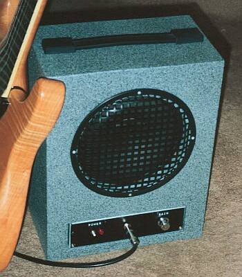
The Final Result
GENERAL CONSTRUCTION HINTS
Wire all the grounds first, using a "star grounding" approach. All subsystems are
grounded to a central tie point, with the only connections to chassis being the input jacks. Care
with grounds is the biggest single thing you can do to insure that your final result is free of
hum. The idea is to prevent any AC current-carrying lines from sharing the same return run with
the signal path. Within a given stage, you use the center-post on the tube socket as a local
ground for signal only; don't share the same local ground with power (i.e. filament) supplies.
Where possible, I mounted parts directly to the tube sockets. The rest of the components were
mounted on perf-board subassemblies. This is a nice way to build, it's more space-efficient than
the conventional terminal-strip approach. I'm not a particularly tidy prototyper, but I must say
that the "Li'l 4x4's" underside looks a lot nicer than, say, the hard-wired version of
my Stand-Alone Phono Preamp. The filter capacitors for the various
supply voltages were glued directly to the chassis using cyanoacrylate cement (Krazy Glue), though
if this offends your sensibilities there's no reason why you couldn't use other approaches, such
as terminal strips.
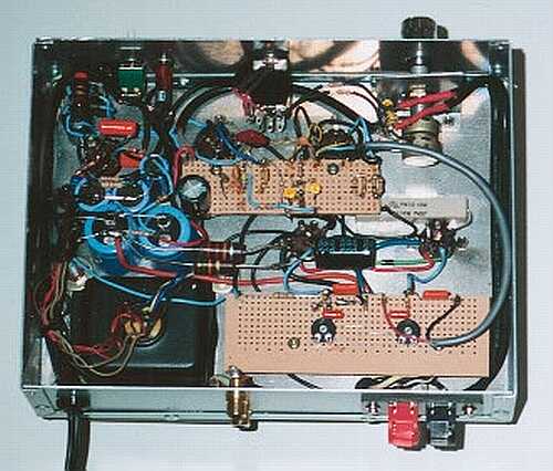
The inner workings of the "Li'l 4x4"
Route power wiring away from signal wiring wherever possible. Be especially careful about the
line-operated filament lines to the output tubes, both for noise and safety considerations. Try to
keep lines as short and "to the point" as possible. Use shielded wire for signal lines,
especially to the input jacks, volume control(s), and between stages. Ground only one end of the
shielded cable runs.
The volume control and line-input jack wiring could use additional explanation. Even though I use
this amplifier almost exclusively as an instrument practise amp, I wanted to include enough
versatility to allow it to be used for other applications. This is the reason for the dual
input jacks and separate volume control sections; a stereo source can thus be connected directly
to the amplifier, without shorting the two signal channels together. The volume control I used
was salvaged from an old stereo unit, in which the two sections are concentric on the same shaft,
and a concentric knob arrangement allows independant adjustment of the two channels as desired.
The output from the instrument amp is also fed into the little passive mixer circuit, for
maximum flexibility.
You could, for instance, run the output of a CD player or tape machine into the line inputs while
playing into the instrument input, so you can play along with a recording to practise your chops.
Or connect the line inputs to your computer's sound card output, for a "Music Minus One"
practise session with a midi file. Carried further, use one line input for the midi, the other
for a synchronised drum machine, all while playing along.
It should be noted that the line "inputs" also operate as "line outs" from
the instrument preamps, for recording purposes or what-have-you. They can even be mix 'n' matched,
use one as a drum machine input and the other as a recording output.
If you don't need the dual input/output facility, you can simplify the circuit by using only a
single volume control, and eliminating the mixing resistors for one of the "channels".
Or go all the way and eliminate the line inputs entirely, if you wish. You can also do away with
the switched instrument input jack, or use a simpler un-isolated switched jack with the switch
arm connected to ground, to effectively short the input when not in use.
I personally have little need or want for tone controls, preferring the pure sound of my
instrument. However, if you feel like it, you can certainly include a tone stack between the
output of the instrument preamp and the line (main) amplifier. An example of a workable stack is
here. You might want a bit more gain in this case; simply
decreasing R39 to 100 ohms and increasing C22 to 22 µF should do the trick. If you need
even more gain, try judiciously increasing the value of feedback resistor R35. Try 470k as a
starting point. In order to maintain bandwidth, you may need to reduce the values of C12 and C13
by about the same proportional amount (e.g. 180 pF.)
There is plenty of room for experimentation with this little design. One of the nice things is that
the components are inexpensive and quite forgiving; as such, this is an ideal project for
learning lots about tubes and sound in general, without the constant fear of blowing up something
rare and expensive. But please - do be careful. Even expensive parts can be replaced; you can't.


