
THE "LI'L 4x4"
by Fred Nachbaur, Dogstar Music ©2001
1: INTRODUCTION
This article documents my quest for a high-quality general-purpose amplifier, using inexpensive
parts. My need was for a clean, accurate instrument (guitar) amplifier, and the resulting unit
suits this need to a tee. I dubbed it "Li'l 4x4", since it is a four-stage amplifier
with an output of a solid 4 watts before clipping.
Before we get into the nuts and bolts of this new design, let's take a little walk down memory
lane and discuss the history behind the tubes and other parts used in the circuit.
History
Prior to the 1940's, home electronics was a luxury only affordable by the relatively well-to-do.
Radio sets were all constructed completely by hand, and even those who could afford them spent
careful hours researching. The arrival of a radio set in the household was easily on a par with
purchasing a new car nowadays; perhaps even more significant in some ways. Those who did purchase
a radio or phonograph often found themselves suddenly quite popular in their neighborhoods, with
friends and neighbors stopping by to socialise and listen.
After WWII, demand for radios and phonographs spurred manufacturers into finding ways of providing
them at costs affordable by the average household. Tubes and other parts were mass-produced, and
engineers found ways of cutting corners -- and thereby costs -- to produce units that were
relatively compact and affordable.
One of most expensive parts was the power transformer. It was also heavy and bulky, making it
difficult to produce electronics that appealed to a growing public interest in miniaturisation and
efficiency. With this in mind, designers found ways of manufacturing tubes that would operate well
directly using the relatively low (by tube standards) home power line voltage - typically 110-120
volts. Another factor was that there were still some regions powered by the otherwise obsolete
DC power grid system developed by Edison; these new radio designs would operate from either type
of supply, hence "AC/DC".
Manufacturers started churning out table-top radios using this new tube technology. Filaments were
wired in series, powered directly from the line, sometimes with additional dropping resistors (or
even line cord with a third resistance wire) as required. Plate and screen supplies were similarly
derived directly from the line voltage. Before long, a great many models hit the market with
essentially the same basic circuit, which came to be known as "The All-American Five"
because of the five octal tubes it utilised. These were:
12SA7 (a pentagrid converter, or heptode, combining oscillator and mixer functions)
12SK7 (pentode, IF amplifier)
12SQ7 (triode and dual diode, used for detection and first audio amplifier)
50L6 (beam pentode, power output)
35Z5 (half-wave rectifier for B+ supply)
The filament voltages of these tubes, when added up, came to 121 volts, which meant that no
additional dropping resistor was required. Because of the directly line-operated power supplies,
the ground return for the power supply was directly connected to one side of the power line.
Since there is a 50/50 chance of having the chassis "hot" (this was before the days
of polarised power plugs), the chassis was isolated from user contact by being placed in a non-conductive
cabinet, with non-conductive knobs. Even so, many models appeared with "phono" inputs,
allowing the connection of a turntable outfitted with a crystal or ceramic cartridge. I'm perhaps
betraying my age by reporting that there were many occasions when I'd get a "tickle"
from the phonograph, necessitating reversing the power plug.
By the late fifties, the new miniature 7- and 9-pin tubes appeared, allowing radios to be made
even smaller and cheaper. The typical lineup in the miniature version of the "All-American
Five" was as follows:
12BE6 (pentagrid converter)
12BA6 (pentode, IF amplifier)
12AV6 (triode and dual diode, used for detection and first audio amplifier)
50C5 (beam pentode, power output)
35W4 (half-wave rectifier for B+ supply)
Here is a typical application of this idea (from the RCA Receiving Tube Manual):
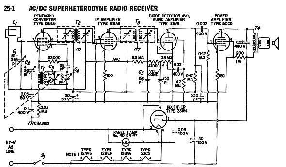
The "All-American Five" circuit using miniature tubes
The output tube, 50C5, was capable of a maximum power output of 2.3 watts, though this maximum
was rarely achieved in real life. Since, as a single-ended circuit, it had to run in Class A
operation, it typically dissipated about 5 watts on the plate, 1 watt on the screen, and 7.5 watts
on the heater, for a total dissipation of over 13 watts in a miniature tube. These things got
hot! Still, they held up very well. There's a machine shop in a town near where I live, that has
a little table radio that's been running continuously since the 60's, and is, to my knowledge,
still on its original set of tubes!
A few manufacturers came up with push-pull outputs, using the 50C5's "cousin", the
35C5. This tube really should have been given a new number, since it is not identical with the
50C5 in other ways than filament voltage. Its filament current is 150 mA, just like the rest of the
tubes used for series heater operation, so with the lower design voltage it dissipated only 5.25
watts. Maximum plate dissipation is similarly somewhat lower (5.2 watts instead of 7) and
maximum output power is given by the manufacturer as 1.5 watts (as compared to 2.3). As for the
50C5, the maximum output power rating is a bit optimistic, and 2 watts was all one could typically
expect from a push-pull pair.
The fly in the ointment, of course, is that two 35C5's plus the other four tubes come up with a
filament voltage of over 140 volts. One solution was to use an early solid-state rectifier called
a "selenium rectifier" instead of the 35W4, and take up the 15 volts excess using a 100 ohm
dropping resistor. Even later, the much cooler-running (and smaller) "top-hat" silicon
rectifiers made their appearance, and were called into service for power supply rectification.
Similarly, the push-pull design required an additional amplifier stage for the phase inverter,
so the dual diode built into the 12AV6 was lost. For radios, a germanium diode was used instead.
Push-pull 35C5's (or even 50C5's) were also commonly found in phonographs amplifiers. These were
essentially stripped-down radio circuits, sans oscillator/mixer and IF strip. I don't have a
picture of a radio to show you, but I do have a couple shots of a phono amplifier that uses
two 35C5's, a 35W4 rectifier, and a 12AX7 dual triode. I'm thankful to Col. Larry Daniel for
providing this, as it makes an excellent "benchmark" against which to compare my new
design.
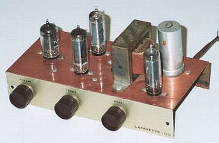
The Lafayette KT-92 phono/tuner amplifier kit, ca. 1959
This was provided by Lafayette Radio as a kit, and appears in their 1959 catalog. The unit I
acquired still works after all these years, requiring only replacement of the filter capacitors and
a couple off-value resistors to bring it back to life, managing to (barely) squeeze out 2 watts of power
on the test bench. It was intended primarily as a phono amplifier, though the input jack says
"Radio/Phono", so it's quite conceivable that Lafayette also offered a radio tuner kit
that could be plugged into this amplifier.

The Lafayette KT-92, wiring side
Here's the underside of the copper-plated steel chassis, showing the typical wiring technique of
the day, employing tube socket pins for connections whenever possible, and terminal strips for
everything else. It sports "tone controls", which by today's standards are almost a
source of amusement; the "Treble" control is merely a high-pass filter at the input,
and the "Bass" control (more properly this would be termed a "high-cut" control) is
a simple high-pass filter in the global feedback network.
This unit actually had a design error*; the on/off switch was placed in the ground return rail of
the AC line. This meant that if you set the power plug to have the ground return "cold"
(i.e. connected to neutral) when the switch was on, the ground would ride high (hot) when shutting
it off, due to the continuity of the tube filaments. This error has been corrected in the schematic
diagram below, also repeated later in the article for easy reference. [* Aug. 2001: see
footnote below].
If you do decide to build a clone of this 1959 Lafayette circuit, either for hobby historical
purposes or as a benchmark for your own designs, please use an isolation transformer.
At the very least, use a polarised power plug (the wider prong is the
ground return). Still, you'll have the devil's own time when interfacing with
other, power-ground-referenced gear because of hum. This is due to the fact that there will
usually be a slight AC voltage drop on your house's neutral line, caused by currents flowing to
lights and applicances in the house. This voltage is effectively added in series with your input
signal, making hum avoidance next to impossible. So, use an isolation transformer and save
yourself a lot of grief, not to mention injury or death.
*FOOTNOTE: Dave Brooks offers this explanation for the apparent wrong polarity on
the AC line: "On the page describing the Lafayette push-pull amplifier kit, you describe
as an "error" the placement of the on/off switch in the chassis AC line. Back in the
1960's, I recall reading an article about the All American 5 design, which (in that instance)
did the same thing. The author explained that this was no error. Given the AC line enters by
the rear of the chassis, and the switch (on the volume control) is at the front, there's
necessarily a length of AC line traversing the width of the chassis. By putting the switch in
the chassis line, this length of AC wire is at ground potential when the set is on, so can't
radiate hum. The hot AC wire is very short, going direct to the HT rectifier and the start of
the heater string."
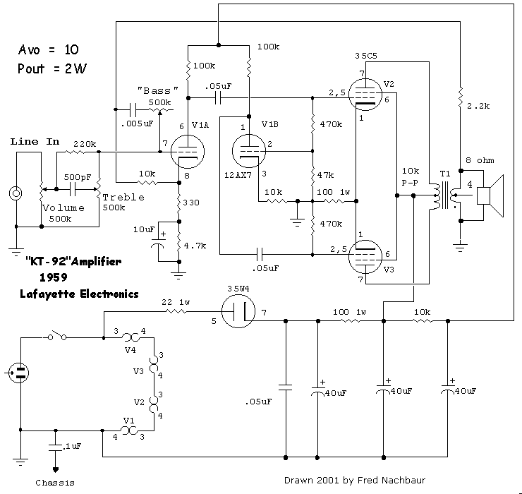
Schematic of the KT92 phono amplifier.
Note that this is an inverting amplifier, phase at speaker is reversed from input phase.


