A HI-FI VACUUM TUBE AMPLIFIER
by Fred Nachbaur, Dogstar Music ©1998, 2000
3A-3: PREAMPLIFIER DC FEEDBACK
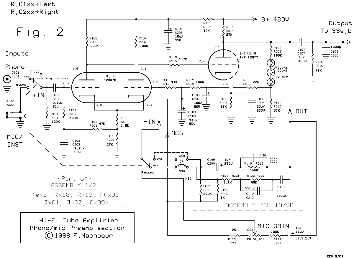
The rest of our circuitry completes the DC feedback loop. In case you're wondering about the
presence of the three NE-2 neon bulbs in series, let's analyze the circuit without them. The plate
of V2 will be sitting at about 315 volts, whereas the grids of V1 are at about 27 volts, or a factor
of about 12:1. We could use a 12-to-1 voltage divider, which would give us a DC closed-loop gain
of about 13. That is, it would require a 13 volt change at the output to compensate for a 1 volt
change at the input.
We can easily improve on this considerably. The lowly neon bulb can be viewed as the tube-
technology equivalent of the zener diode. That is, the voltage drop across the bulb (typically
about 65 volts) is reasonably independent of the current passing through it. The three NE-2's can
therefore be viewed as a 200 volt "level shifter," allowing us to use a much lower voltage division
ratio (about 4:1) in our DC feedback loop. The result is an almost 3 times improvement in DC
operating point stability.
The level-shifted and divided output voltage goes through a two-stage low-pass filter consisting of
R111, C105, R112 and C104. This strips AC signals from our DC feedback loop, to insure that the
amplifier will still have full open-loop AC gain. The resulting DC feedback voltage is applied to the
inverting input of our differential amplifier via R113. The junction of R113 and C104 also forms a
convenient "AC Ground" point for our signal feedback networks.

Phono and Mic/Line Preamplifier
Let's step through what happens if some change occurs in DC operating point. This change could
be caused by tubes and other components aging, power supply voltage fluctuations, or input
overdrive conditions. Let's assume that the change causes the output voltage to rise, as would be
the case as V2's emission decreases. This would cause an increase of bias voltage (more positive)
on the grid of V1B (the feedback input), causing that stage to draw more current and increase the
voltage on the common cathode. V1A (our input stage) would therefore draw less current, causing
the voltage on its plate (and therefore the grid of V2) to increase. This would cause an increased
V2 plate current, resulting in a decrease in plate voltage, tending to buck the original change.
See how the overall circuit is self-regulating?
Resistor R114 forms the plate load for V2, and C107 couples the output to the tone/line preamp
module via the input and tape monitor switches. Capacitor C108 provides another pole of high-
frequency attenuation (compensation) to prevent oscillation at low gain. (Before I added this
additional compensation, the first prototype became a dandy 11 megahertz transmitter at gains
lower than about 3!)


