A HI-FI VACUUM TUBE AMPLIFIER
by Fred Nachbaur, Dogstar Music ©1998, 2000
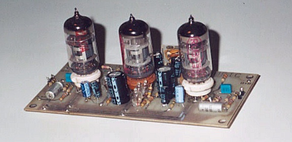
A photograph of the Universal Preamp Module,
configured for phono and tone amp use
3-B) PRE-AMP DIFFERENTIAL INPUT STAGES
Each of the modules (Phono/mic, Tone/line, and Driver/PA) uses a differential input stage, giving
us both an inverting and a non-inverting input and affording additional useful and beneficial
features. The following discussion relates directly to the Phono/mic preamps (refer to Figure 2),
but applies by extension to the other modules also.
Phono and Mic/Line Preamplifier
The appropriate input signal is coupled from the phono or mic input jacks, through switch SW2, to
the grid of the first section of V1 (a 12AX7A vacuum tube) via coupling capacitor C101. Since this
grid is at a substantial DC voltage above ground, resistor R101 is used to insure that the input is
always at DC ground potential. Note that, as far as the input AC signal is concerned, this 100K
resistor is effectively in parallel with R102 (also 100K), giving us the 50K input impedance
required for most magnetic phono cartridges.
The two triode sections of V1 are used as a differential amplifier. Note that the cathodes are tied
together, and go to ground via a relatively large shared cathode resistance consisting of R104 and
R105. This acts as a rudimentary constant-current source. If the current in either triode
increases, a comparable amount of current will be robbed from the other triode. Therefore, if the
voltage on the signal input increases (goes more positive), plate current increases and the plate
voltage of that triode will drop, while the plate voltage of the other triode increases by about the
same amount. However, if the voltage on the feedback input increases, causing an increase in
current in that triode, the voltage on the plate of the first triode section will increase and that of
the other triode will decrease.
A portion of the cathode resistor voltage drop is sampled by R104, low-pass filtered by R103 and
C102, and provides the grid bias for the first section of V1 via R102. An interesting feature of this
circuit is that this also sets the bias and operating points for the entire amplifier, as we'll see as
we progress through the analysis.
Experienced electronicists will be quick to point out that a simple cathode resistor is not an ideal
current source. As a result, the "common-mode rejection ratio" (that is, the gain matching of the
two inputs) of this circuit is quite low. (A great improvement results by using a pentode as a
current source in the differential amplifier cathode circuit, a trick that's used in the driver stage
where common-mode reduction is more critical because we also require balanced outputs.)
What we do instead, in the preamp modules, is "cheat the system" and carefully choose the
operating points of the two triodes to be different, to help offset the error. Note that, even though
there is approximately the same current flowing in the plate circuit of each triode section (about
500 microamperes), the plate voltage on the second section is considerably higher (by about 90
volts) than the plate voltage of the first section. This is because of the lower value of plate
resistor R107, as compared to R106. This "trick" assumes that the two sections of the tube are
reasonably well-matched, and will furthermore track as the tube ages. Tests with different tubes
of varying manufacture and condition have verified that this assumption is indeed valid.


