A HI-FI VACUUM TUBE AMPLIFIER
by Fred Nachbaur, Dogstar Music ©1998, 2000
3A-5: PREAMPLIFIER PHONO, CD and MIC/LINE FEEDBACK NETWORKS
Ceramic phono and Mic/Line
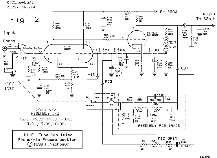
The feedback network for the Ceramic phono input is little more than our "bare bones" network
described above. R118 in series with C109 forms our Zf . R119 is added as a refinement to insure
that the negative end of C109 is always held at the DC potential of our feedback input,
eliminating the massive pop that would otherwise result when switching modes. Note, however,
that it is effectively in parallel with R113, lowering our Ri value to 38.7K. You can verify that our
closed-loop gain would therefore be (150/38.7)+1, or about 5. Input resistor R123 attenuates our
input signal by a factor of about 3:1, so the overall system gain is a little less than 2 (5 dB).
The final element is C110, which introduces a 3 dB corner at about 20 kHz, rolling off ultrasonics
that we aren't interested in. (Without this capacitor, the gain is actually flat to well beyond 100
kilohertz! See how feedback got rid of that open-loop corner at 2 kHz?)
The mic/line feedback network is similar, except that the gain is variable over a considerable
range (about 2 to 200) by the gain trim pot.

Fig. 2: Phono and Mic/Line Preamplifier
Magnetic Phono
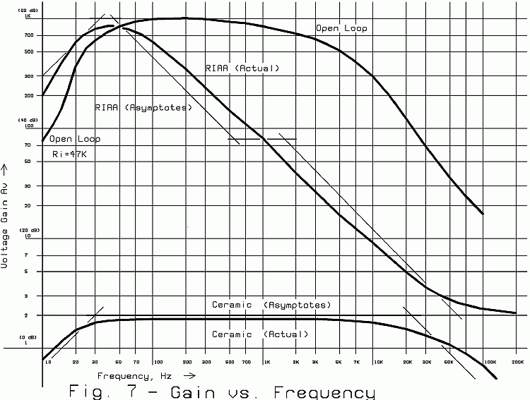
The magnetic phono feedback is only a little more involved. The straight thin lines in Figure 7
show the theoretical RIAA specification (asymptotes), and the curve shows the actual response of
our preamp in this mode.
Note that, in the bass region, our preamp has to run open-loop in order to get the required 60 dB
gain. Our feedback network therefore doesn't even have to bother with the poles in this region.
Instead, R120 was chosen to present an appropriately low value for Ri . The effect is to further
"swamp" any low frequencies that manage to make it through the DC feedback filter consisting of
R111, C105, R112 and C104. This pushes our low-frequency "hump" to exactly where we want it.
As frequency increases, at about 50 Hz., C111 comes into play and acts as an integrator to roll off
our response. At about 530 Hz., the pole consisting of C111 and R122 tries to level the response,
and at about 1600 Hz. C112 and R122 introduce the second roll-off section. The net result is a
gradual rolloff over the audio range at a somewhat gentler average slope (about 4.5 dB per
octave) than would be achieved with a single-pole integrator (6 dB per octave). Finally, R121
limits minimum gain to about 6 dB at ultrasonic frequencies, helping to insure stability.

Fig. 7: Preamplifier Open-Loop and Phono Gain Curves


