April 30, 2002
Part 3: HT Supplies and Regulators
Auxiliary supplies:
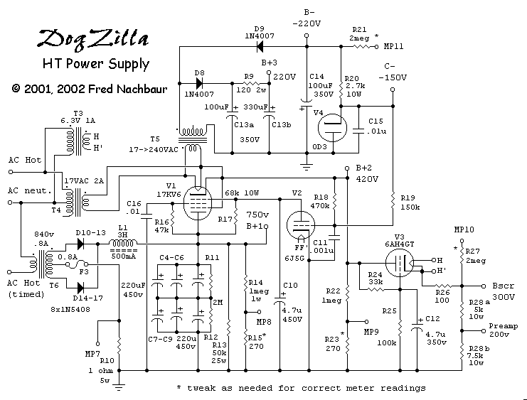
Constant (untimed) AC is applied to the secondaries of two more filament transformers, T3 and
T4. These are for valves V1 and V3, respectively; both of these valves operate
with their cathodes at several hundred volts above ground, and therefore require isolation to prevent
cathode-to-heater arcing.
The secondary of T4 is also connected to the "secondary" of T5, an identical
17V, 2A transformer with dual (120V / 240V) primary scrounged from junked handheld 2-way radio
battery chargers. T4 steps the 120VAC line voltage down to 17 volts, and T5 then steps
this 17 volts up to (nominal) 240 VAC. This is rectified and filtered by D8 and C13 to
provide a low-current 220VDC supply, to power the "small-amp emulator" and also provides
the B+ for the voltage follower stages for the power amplifier.
Another rectifier/filter consisting of D9 and C14 provides a negative 220V supply. This
provides bias for the 0D3 -150 volt regulator, V4 via resistor R20. Capacitor C15
provides a bit of noise reduction on the regulator. While this tube operates much like a zener diode,
it's important to point out that only small parallel capacitances are allowed; otherwise the circuit
becomes a relaxation oscillator. This -150 regulated voltage supplies the negative grid bias for the
voltage followers (and hence the final PA tubes), and also forms the reference for the positive
regulators described later.

Schematic, HT Power Suppies
Main B+ Supply:
Timed AC input is applied to the primary of the plate transformer T6, a very substantial piece of
iron that I was fortunate enough to horse-trade with my old pal Peter McMullin (thanks Peter!). This
is a military-surplus transformer manufactured by Hammond, with multiple primary taps allowing trimming
to the output voltage desired. The taps chosen ended up producing 840-0-840 volts RMS at a load of
400 mA. Diode strings D10-13 and D14-17 (a total of eight 1N5408's) are conventional
full-wave rectifiers, with plenty of voltage headroom.
A choke-input filter consisting of L1 (Hammond 193N, 3 Hy 0.5A) provides about 750 volts
under quiescent conditions, sagging not much lower than about 720 volts under full power. This project
has given me a profound appreciation for choke-input filters, despite its high power capability the
power-supply hum in the finals is completely inaudible. The capacitor bank consisting of
C4-C9 provides the main energy tank, with a total capacitance of 330 uF this gives storage
of 93 joules at 750 volts. Resistors R11 and R12 provide a bit of added insurance to
equalise the voltage drop across each half of the bank, in the event that internal leakage currents
should drift. R14 and R15 are a voltage divider for the metering circuit. R13
is a 15 mA. bleeder resistor, which insures that output voltage will not soar above the 900 volt
rating of the filter capacitors during no-load conditions (as could be caused by a circuit fault,
or operator indiscretion).
+420 Volt Active Regulator
The main +420V B+ supply for all the preamplifier sections is derived from a pretty straight-forward
active regulator consisting of beam pentode V1 (a 17KV6 or similar "deflection tube"),
V2 (a generic medium-mu triode such as 6J5 or 6C5), and reference V4. V1 is
essentially a voltage follower (common anode amplifier); the voltage at the cathode will be close
to the voltage on the control grid. The anode of V2 is connected to this grid, and is biased
by plate-load resistor R17.
The output voltage at the cathode of V1 is sensed by the voltage divider consisting of
R18 and R19. The bottom end of R19 is connected to the -150 volt reference, and
the divided output is applied to the control grid of V2. This forms a DC negative feedback
loop which regulates the output voltage within a few volts, over a wide range of output current.
The network consisting of R16 and C16 provide a rudimentary screen supply for the
pass regulator V1. Capacitor C10 has the effect of having its capacitance effectively
multiplied by the mu of the pass regulator, providing additional hum suppression. Capacitor C11
limits high-frequency response of the circuit, for stability.
+300V Screen Regulator:
Finally, valve V3 forms a simple pass regulator for the screens of the output tubes. Again,
it is essentially a voltage follower, referenced to about 3/4 of the voltage from the main
regulator by the divider consisting of R24 and R25. Again, the circuit effectively
multiplies the capacitance of C12 for further hum reduction. A slight amount of local
feedback (empirically found necessary for overall stability) is provided by cathode resistor
R26. Similarly, screen bleeder resistor R28 is added as insurance against
instability potentially caused by secondary emission of the screen grids. R27 forms the
dropping resistor for the metering circuit.
A late-breaking development (August 2002) was to split the screen bleeder resistor into two
sections, R28a and R28b to provide a fairly stable 200 volt supply for the
first-stage preamp. The other "raw" B+ supply can be expected to sag somewhat
with "small-amp emulator" overdrive conditions, and is therefore suitable for
later cathode-follower stages and such, but for the critical first stage a bit more
stability is desirable. Hence, the old voltage divider trick.


