May 13, 2002
Part 6: Active Tone Control and Limiter
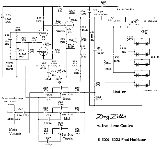
Continuing to step through the circuit backwards, here is the active tone control and
limiter circuitry. The active tone control is yet another incarnation of my "universal
quasi-opamp preamplifier" design, and is in fact almost identical to the circuit used in
my RA-100 stereo hi-fi amplifier. Open
this link in a new window to step through the design
description of this circuit, then close the window to return here.
Active Tone Control:
This tone control circuit gives up to about ±12 dB of boost or cut to bass,
midrange and high frequencies, by placing a garden-variety triple-T network in the
feedback loop of a two-stage, direct-coupled amplifier consisting of V13
(12AX7) and (12AU7).
This (and the Marshall Tone Stack line amp to follow) is essentially yet-another
incarnation of my "Universal Preamp" design, with the exception that a 12AU7
is used for the output stage in order to accomodate the larger required output swing.
The lower gain that results is not important in this application.
The image below is a bit more involved than usual, so to accomodate lower screen
resolutions the version below has been reduced somewhat. You can right-click on the
image, then "open in new window" to view the full-size image.

Schematic, Active Tone and Limiter
Right-click to open full-size image in new window
To step through the circuit briefly (for those who don't want to read the
full version), input to the stage is applied to one side
of the triple-T network. The other side goes to a divided-down (via R75 and
R76) sample of the output signal (via blocking capacitor C31, and the
junction of the centres of the tees connects to the "inverting" input of the
amplifier, completing the AC feedback loop.
The non-inverting input of the amplifier is grounded for AC by C36. However, this
could be used as an auxiliary input if the need or want is there. A
rather fancy biasing arrangement consisting of resistors R87 through
R90 and capacitor C35 sets up the first stage as a short-
tail pair differential amplifier, whose output is coupled directly to
the grid of second stage V14a via grid-stopper R81.
The second stage's plate load is provided by R77, and its cathode
resistor R80 is bypassed for audio by capacitor C34. The
output signal is coupled to the limiter circuit via C30. A rather
nifty DC feedback loop sets the overall operating point of the amplifier
via a divider/ level-shifter consisting of R78, R79 and
NE-2 neon lamps L1 through L3, and a low-pass filter
consisting of R84 through R86 and capacitors C32
and C33.
R73 and C28 decouple the second stage from the 430v
regulated power supply, and R74/C29 provide further decoupling
for the first stage. (In case you haven't noticed, I believe in
decoupling each stage within an inch of its life. There are enough
things to worry about when debugging, and decoupling each stage is a
great way to stack the odds in your favour.)
Dynamic Limiter:
Before describing the limiter circuit, an explanation of the difference
between a "compressor" and "limiter" is in order,
since DogZilla sports both features.
A compressor dynamically alters the overall gain of an amplifier,
according to the average audio level. At higher average levels, it
decreases the gain, giving a narrower dynamic range by making loud
signals significantly quieter. A compressor therefore does not
significantly alter the overall wave-shape of the applied signal. A
compressor is a terrific add-on for playing in a band situation, where
you want a more-or-less constant average level in relation to the other
instruments.
A limiter, on the other hand, applies a non-linear transfer function to
the waveform. The higher the amplitude, the more the response
"flattens out." This has the effect of gradually introducing
distortion, of a type that is much smoother and warmer than hard
clipping distortion. In fact, it can be viewed as a graduated clipping
mechanism; the louder you play, the more pronounced the overdrive
distortion becomes.
The other significant effect that a limiter has, compared to clipping
distortion, is that detail in the clipped portion is retained. In other
words, if you play a chord, a limited version will still contain all the
notes of the chord, and will not degenerate to a "power chord"
consisting only of the tonic and its overtones.
The limiter in DogZilla consists of a ladder of ordinary silicon signal
diodes D10-D19 and resistors R68-R71. (I had
planned on doing this using tubes, but the added complexity just wasn't
worth the effort.) Each pair of diodes represents a step in the progressive
limiting effect, and the resistors define the overall shape of the resulting
transfer function. The values shown here are customised for Dogzilla's driver
stage sensitivity of about 3.5v peak, using a combination of simulated and
empirical experiments to arrive at a smooth and easily-managed limiting curve.
With the limiter switch turned off, the output from the active tone
preamp is applied to the driver preamp, via the voltage divider
consisting of R72 and the input impedance of the driver preamp,
giving about a 6 dB attenuation. When the switch is turned on, the
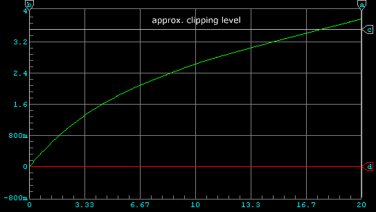
response is identical at voltages less than about 0.6 volts peak. Beyond
that, each diode/resistor element gradually comes into play, giving the
transfer function shown in the image below:

Limiter Circuit Transfer Function
Here's another way to look at what it does, using a real-time signal; in
this case, a sine wave with a peak level of 10 volts. Note that this is
divided down to about 5 volts peak, which is a high enough level to drive the
PA significantly into clipping.

Sine wave, limiter off
Now, let's turn on the limiter. Note that the wave has been
"squashed", placing the peaks well below the clipping level of
about 3.5 volts. What's interesting is that because of the increased
area under the curve, it doesn't actually sound that much quieter
than the non-limited version. It therefore lets you apparently play louder,
while still staying below hard clipping.

Sine wave, limiter enabled
Whereas the amplifier starts clipping at about 7 volts peak (at the
output of the tone preamp) with limiter off, clipping doesn't occur
until about the 20 volt peak level with the limiter on. This represents
about a 9 dB limiting ratio, certainly not an insignificant factor!
By changing R72 the threshold can be controlled. Higher values
could assure that the tone amp reaches clipping before the power amp
does, and lower values could be used to soften the effect. The value
shown is a reasonable compromise.


