The Real McTube II
by Fred Nachbaur, Dogstar Music ©1998, 2001
3: HOW IT WORKS
120 volt AC power is applied via power on-off switch S1 to the primary of transformer T1 and
"power on" indicator I1, a neon lamp with built-in series resistor. T1 is scrounged
out of an inexpensive 12-volt, 500 milliamp "wall-wart" DC power supply.
The (nominal) 12 volt AC output of T1 is rectified by a full-wave bridge rectifier (D5-D8),
which can be individual diodes salvaged from the same "wall-wart" supply, or if you
prefer you can use an encapsulated button-style full wave bridge assembly. The resulting
120Hz pulsating DC is then filtered by the network consisting of C3, R2 and C4. The drop
across R2 also reduces the filtered DC voltage to about 13 volts, to supply 150 milliamps of
relatively clean DC power for the tube's heater. This results in a significant reduction of AC
hum as compared to the original "Real McTube", which used AC to directly heat the
tube's filaments.
The 12 volt AC output from T1 is also coupled into an identical transformer T2, wired
"backwards." This steps the voltage back up to about 110 VAC for our plate
supply. DO NOT omit this transformer! Although the circuit will work if you derive
the 120 VAC directly from the line, you could seriously injure or even kill yourself
or somebody else. (If that's not enough disincentive from isolating your B+ supply, you can
also ruin the gear to which an unisolated piece of equipment is attached!)
Diodes D1-4 full-wave rectify our B+ voltage. As is the case with D5-D8, these can either be
four discrete 1N4004 diodes, or a 400V 1A button-style full-wave bridge module. (Note that in
this case it's not usually possible to use the diodes from the "wall-wart", as they're
usually 1N4001 or 1N4002 units, not capable of withstanding the higher AC voltage.) Capacitor
C1 filters the resulting pulsating DC, and the network composed of R1 and C2 add a pole of
low-pass filtration to reduce ripple. The end result is about 140 volts DC under load to power
the plate circuits of our preamplifier.

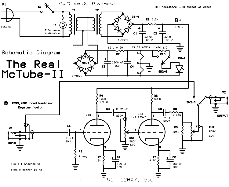
Schematic, The Real McTube.
(Click on image for enlarged version, or right-click to open in new window)
The input signal from J1 is coupled to the grid of the first stage via capacitor C5.
Input resistor R3 acts as a "grid-leak" to prevent any electrons accumulated on
the grid from piling up on C5; the resulting negative voltage would eventually cause our
tube to approach cut-off. The value was chosen to be high enough to not cause any
significant loading on the input signal, while being low enough to assure that the grid
is "biased" very near to ground potential.
R4 is our plate load resistor. The varying plate current flowing through this
resistor causes a voltage drop proportional to the change in current. R4
therefore plays a major part in defining the voltage gain of our amplifier stage.
Experiment! (Suggestion; to prevent possible damage to the tube and/or power
supply, don't go lower than about 22K for R4 or R6.)
The plate current also flows through cathode resistor R5, causing a much smaller
voltage drop across it. The result is that the cathode is slightly positive with respect to
ground, and since the grid is approximately at ground potential, it follows that the
grid will be negative with respect to the cathode. This is how we get the
necessary negative grid bias, obviating the need for a third power supply. This scheme also
helps to stabilise the circuit against changes in line voltage, tube aging, etc. by adding
a bit of DC feedback. For instance, if line voltage drops, causing a decrease in plate current,
the bias voltage will decrease also, tending to buck the decrease in plate current.
Capacitor C7 "shorts out" any signal component, eliminating the negative
feedback (for AC) that would otherwise result. This has two major effects: first, it
maximizes voltage gain, making it easier to achieve overdrive. Secondly, it
eliminates any reduction in non-linearity distortion which would defeat our
purpose in getting "that tube sound." Again, experiment. Remove C7 - you'll have
less gain, but see how much cleaner the tube sounds? Short the cathode directly to ground -
see how much dirtier the sound gets as the grid is driven into conduction?
The signal output at the plate of the first stage is coupled into a similar stage by
capacitor C6 and GAIN control RV1. The component values in the two stages
were chosen more or less experimentally to suit my own tastes. I suggest that
you use these values as a starting point, and ... again ... experiment.
The output of the second stage is routed through an attenuator consisting of R8,
R9 and "OUTPUT" control RV2. The accumulated gain after the second stage is
so high that the absence of an attenuator would make it ridiculously difficult, if
not impossible, to adjust the controls for varying degrees of overdrive, let alone balance the
overdrive signal with the unmodified signal when in "bypass" mode. The wiper
of RV2 is the output of our circuit, which passes via the contacts of bypass switch SW-2a to
output jack J2. The other pole of the switch (SW2-b) is used to light LED1 to indicate that the
overdrive / distortion mode is enabled.
When SW-2 is in the other position, the output jack is connected directly to the input,
effectively bypassing the entire circuit. (The 1 megohm of loading by resistor R3 will be
negligible, and the net effect is as if the circuit isn't there at all.)


