The Real McTube II
by Fred Nachbaur, Dogstar Music ©1998, 2001
2: BASIC TUBE THEORY
Vacuum tubes (or "valves", to use the more functionally descriptive British term) are
"active" devices (as opposed to passive devices like resistors and capacitors) which,
until the advent of solid-state devices, were the only viable means for constructing virtually
everything electronic: from simple rectifiers, to amplifiers and oscillators, even logic circuitry.
In principle, at least, anything that can be done with solid-state devices could be done using
tubes. In practise, however, their size, power requirements, and speed limitations would make many
of the devices we now take for granted (such as the computer on which you're viewing this document)
impossible. Nonetheless, they still have an honoured place in today's world, as this project will
hopefully demonstrate.
Probably the most important member of the family of vacuum devices we refer to as "tubes"
is the vacuum triode. This is the simplest vacuum device that is capable of amplification; i.e.
providing an output signal greater than, and roughly proportional to, an applied input signal. In
this respect it is functionally analogous to the ubiquitous transistor.

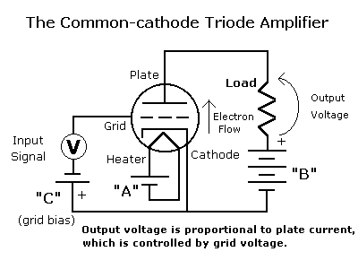
Unlike transistors, however, tubes require at least two power supplies. Before the advent
of universal home power, most electronic gear was operated on batteries. One
battery (called the "A" battery) was needed for the low voltage, relatively high
current supply to heat the tube's filament. Another (the "B" battery) was the high
voltage, low current battery used to power the tube's plate circuit. This
anachronism has persisted to this day; if you ever wondered why you hear of
devices connected to "B+", now you know. In the early days, there was even a
"C" battery, used to provide the negative grid bias for some circuits. This didn't
persist for very long except in special radio applications because the negative
grid bias can usually be obtained by using a cathode resistor, as in our circuit, or by other
means.
Vacuum triodes are roughly analagous to field effect transistors (FETs). The "cathode" is
analogous to the source, the "grid" to the gate, and the "plate"
to the drain. Like FET's, tubes have a near-infinite input impedance, and a high output
impedance. The most widely-used tube configuration (common cathode) is quite similar to
the common-source FET amplifier configuration. But there the similarity ends.
Physically, a tube operates by heating the "cathode", one of the electrodes
inside the vacuumized envelope. This causes electrons in the cathode to attain
enough velocity to leave the surface, forming a "space charge" around the
cathode. The positively-charged "plate" (also sometimes called "anode"),
usually surrounding and concentric with the cathode, attracts this space charge, causing
an electron current to flow through the space between the cathode and plate. If
the plate is negatively charged, the space charge is repelled and no current
flows; this is how the vacuum diode works. Such vacuum diodes were once almost universally used
as rectifiers in power supplies, detectors in radio circuits, and similar applications.
In what's called a vacuum triode, there is another electrode called the "grid",
placed between the cathode and the plate, consisting of a spiral screen of fine
wire. The grid is normally biased negatively, so that it does not act as a
secondary plate and draw current. Small changes in voltage on the grid cause
significantly greater changes in electron current through the tube from cathode to
plate, resulting in amplification.
As the tube was developed, additional grids were added to form first the
"tetrode", which has a second grid (at a positive potential) to act as an intermediate
"plate", resulting in a more constant-current characteristic. The problem with
tetrodes is that the relatively high electron velocities caused "secondary emission"
caused by electrons being bounced off the plate. The "pentode" overcame this by
adding another grid (at a low potential) between screen and plate. The culmination of
multi-grid mania was the "heptode", which is not a cool frog but rather a five-grid
device once used extensively as the oscillator/mixer in home radio receivers.
When dealing with vacuum tubes, it can make sense to consider current flowing
from the negative terminal to the positive terminal of the "B" supply, because
that's what physically happens. This is called the "electron current" convention,
and was what was taught in most technologist courses up until a couple decades
ago. The problem with this convention is that the algebraic signs end up
backwards in circuit design and analysis, so engineering courses thankfully used
the opposite convention (called "conventional current flow") in which current is
assumed to flow from positive to negative. This has the advantage in
semiconductor circuits of making the arrows in diode and transistor symbols
point in the right direction. When dealing with tubes, however, which convention
you use is strictly a matter of personal preference.
Finally, I should point out that unlike transistors, tubes come in only one polarity
because we only have one type of charge carrier - electrons. Unlike the solid
state, no one has yet figured out how to make holes in a vacuum. I suppose it's
theoretically possible to make tubes out of anti-matter to get "PNP" tubes, but
storage and interfacing could be a bit of a headache. ;-)


