A HI-FI VACUUM TUBE AMPLIFIER
by Fred Nachbaur, Dogstar Music ©1998, 2000
3D: POWER SUPPLIES
3D-1: Power Supply for full stereo Integrated Amplifier
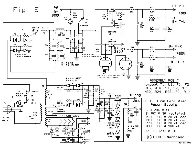
Both channels share a single power supply (see Figure 5). Transformer T1 provides 500-0-500
VAC for the plate supplies, 6.3 volts for most of the heaters, and 5 volts for the driver heaters. (A
second 6.3V winding would have been preferred, but as designed the driver works fine at a 5 volt
heater supply. More about that in the "Tweaks and Hacks" section.)
The "raw" B+ is filtered using a capacitor-input CLC pi filter, with values chosen for the best
tradeoff between regulation, output voltage and ripple. A reference voltage of about 230V is
supplied by two 0B2 gas-tubes in series, and is used to derive the regulated 230V line for the
driver stage (via a transistor regulator in the emitter-follower configuration). These gas tubes
could be replaced by series zener diode strings, but isn't recommended because of the tendency
of high-voltage zeners to drift with temperature. We need a stable reference voltage here, to
prevent PA grid bias from drifting. There's no need be concerned with the "noisy"
aspect of the gas tubes, since the differential pairs in the PA drivers will tend to cancel out
such noise.
An only slightly more involved regulator circuit supplies the 430 volt B+ for the four preamp sections. Each of
these are thouroughly decoupled, first on the main power supply board and then some more on
the two preamp boards. You may be asking, "Why such a fancy regulator, if you're just
following it with CRC filters anyway?" If so, you have good design instincts. The preamps,
by virtue of the self-levelling DC feedback design, are very forgiving about supply voltage
fluctuations, and will indeed work fine anywhere between about 400 and 450 volts. A suitable
series resistor would therefore be all it takes to derive their supply voltage from the 600V raw
B+ line.
However, there is a potential problem during warm-up, before the preamp stages draw any plate
current. Unless you appropriately increase the voltage rating of all the electrolytic capacitors
on the preamp board to accomodate up to almost 700V during warm-up, you could cause serious trouble.
The inclusion of a regulator consisting of two inexpensive transistors and three resistors is a
much smaller price to pay.

Fig. 5: Full Amplifier Power Supply
The driver stage is direct-coupled to the PA grids, imposing special requirements. Since PA grid
bias and balance are set by varying the driver currents, the well-regulated positive supply (230V)
is a must. In addition, a reasonably well-regulated negative supply is needed. The reference for
this is supplied by a string of zener diodes, to reduce size and cost. (We could just as well use a
string of gas tubes, as we did for the positive supply. However, such a large voltage drop would
have been bulky, expensive, and wasteful of power, since gas tubes typically need to draw at
least five milliamps for good regulation.) Another transistor voltage-follower provides the
regulated -550V rail for the drivers.
The simple negative supply regulator is actually one of the few areas of the design that I'm not
completely happy with. High-voltage zener diodes tend to be quite sensitive to changes in
temperature, meaning that the regulated voltage can easily drift over a range of ten volts or
more. The result is a wandering grid bias; not fatal to the design by any means, but not ideal
either. However, it does work adequately. You might ask why we don't use a similar approach to
that of the positive regulator, where a lower voltage reference is divided up. The answer is that it
is difficult (if not impossible) to find PNP transistors with the requisite 500V+ breakdown voltage.
I therefore left the circuit as-is for the published design, and am including a fix in the
"Tweaks and Hacks" section. If you're a closet purist, you'll
be a lot happier with the modified version.
The filament supplies for the preamps are rectified and filtered, giving reasonably clean 6.3V DC
to substantially reduce hum and noise induced from the filaments to the control grids of these
tubes. They actually consist of two separate half-wave supplies, one for each channel; one supply
positive, and the other is negative (relative to ground). The reasons for this unusual approach
are: A) Since our power meters require a ground-referenced supply, one side of the filament
transformer must be grounded. This eliminates as an option the common solution of having a
tapped "hum balance" pot between floating filament lines. B) This circuit is essentially a voltage
doubler, allowing us to use a low-current 12-volt cooling fan such as is used for computers, etc.
(an absolute necessity if enclosing the amplifier in a cabinet).
Note that the power on/off switch is a double-pole unit, with the second pole used to switch in a
3.3K "bleeder resistor" to the main positive supply. Don't omit this if you build the amplifier. It
serves a dual purpose: 1) to help protect you from shocks from charged capacitors when working
on the unit, and 2) to insure that the positive supply drops before the negative supply does,
quickly driving the output tubes into cutoff on power-down and eliminating the possibility of nasty
turn-off transients.
The "Standby" switch is also highly recommended, even if you install the "hack" to eliminate its
need in actual operation. The reason is that it allows you to safely set final grid bias without any
possibility of damage to the pricey 6L6GC's and associated circuitry.

The Power Supply for the RA-100 Amplifier


