| Intro | Features | Copyright | Index | Resources | Contact |

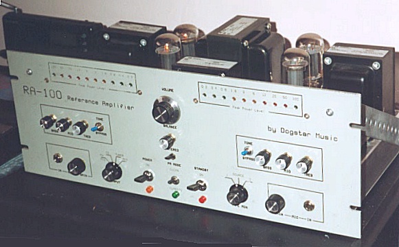
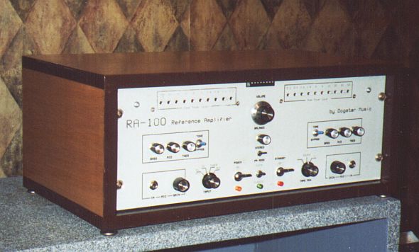
The completed RA-100 amplifier in operation. Click here to view the specs.
|
Build the "RA-100" High-performance Vacuum-tube Reference Amplifier |
|
The RA-100 integrated amplifier design was almost three years in the making, being
completed with a fully operational prototype on the eve of the third millenium (December,
2000). It uses a novel design approach, in which modern op-amp design techniques are
combined with classic vacuum-tube knowledge to produce a circuit that represents a
significant improvement over most classic audiophile-level tube designs.
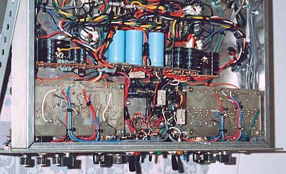
This project is recommended for advanced electronics experimenters only. It uses potentially dangerous voltages, and includes some relatively expensive parts that can be destroyed through mis-application. The information provided here is believed to be correct, but the author and Dogstar Music assume no liability for damages incurred through use or misuse of the information provided herein. With the disclaimer out of the way, I can only add that those with the know-how, experience, time and tenacity to tackle this project (not to mention the several hundred dollars in parts!) will be rewarded with an excellent, near-studio-quality piece of gear that will be cherished for many years. Photos of the prototype are interspersed throughout the site as appropriate, or may be viewed at the Photo Gallery Page. |

|
Features:
Copyright Notice: All contents of this website, including all schematics, text, diagrams and photographs are Copyright ©1998, ©2000 by Fred Nachbaur, Dogstar Music. All rights reserved. This site may be freely linked, but none of the contents may be posted anywhere else without express permission of the copyright holder. The information presented here may be used for personal, non-commercial use only. Any commercial applications of this design or any part thereof requires previous licensing arrangements with the author and copyright holder, Fred Nachbaur. Article Index: Note: the pages on this site contain inline images to aid in understanding the operation of the project. Most such images (with a border) can be viewed in an enlarged version (1200 pixels wide) by clicking on the image. Alternately, you can right-click to open the enlarged image in a new window. For best results, this site must be viewed at a screen resolution of 800 x 600 or better (1024 x 768 recommended). If you are running 1260x1024 resolution or greater, you can switch to high-resolution mode, with larger inline images, by clicking on the link below: 1: Introduction 2: Design Philosophy 3: How It Works A) Preamplifiers 1: Differential Input Stage 2: Output stage 3: DC Feedback 4: AC Feedback 5: Phono, CD and Mic/Line Feedback Networks 6: Tone Control Networks B) Other Pre-amp applications C) Drivers and Power Amplifiers D) Power Supplies 1: Power Supply (full) 2: Power Supply for standalone preamps E) Output Power Meters 4: Construction hints 5: Parts List 6: Tweaks and Hacks Addendum Sept. 2002: Improving the LTP/CSS Driver Circuit Resources: Following is a listing of available resources (schematics and other diagrams) necessary for construction of the complete amplifier, or stand-alone pre-amplifier units. These are provided as GIF files, intended to be printed to letter-size paper, Portrait layout, with an image size of exactly 7.5" x 10". The complete article as published on this website is also available in PDF format (Acrobat Reader required). The "Figures" are not embedded, as I've found this can cause trouble on some printers; you will still need to download the GIF images. The "Artwork" (PC board layouts and chassis templates) is also available as a single ZIP file containing the needed images. |
| Document: | Figure: | Filename: |
| Full Article (as per 1-6 above) | N/A | amptext.pdf rev1.5, 8 Feb 03 |
| Addendum (Improving LTP/CSS Driver) | N/A | driver02.pdf 3 Sep 02 |
| Artwork (PCB layouts, templates) | N/A | artwork.zip rev. 15 Jul 02 |
| Amplifier Block Diagram | Figure 1 | ampblokl.gif |
| Phono/Mic Preamp Section | Figure 2 | preamp-l.gif |
| Tone Control Preamp Section | Figure 3 | toneampl.gif |
| Driver and PA Section | Figure 4 | pwramp-l.gif |
| Full Amplifier Power Supply | Figure 5 | pwrsupl.gif |
| Power Supply for Standalone Preamp | Figure 5a | prepwrsl.gif |
| Preamp Gain vs. Feedback ratio | Figure 6 | pregainl.gif |
| Preamp Frequency Response | Figure 7 | prefreql.gif |
| Other Preamp Applications | Figure 8 | premodsl.gif |
| Output Power Meters | Figure 9 | meterl.gif |
| Increasing Driver Heater Voltage | Hack 1 | hack1l.gif |
| Stabilising -590V Regulator | Tweak 2 | tweak2l.gif |
|
Contact:
You may contact me regarding this project at fnachbaur@netscape.net. I'd be happy to hear from you, and any bug reports or suggestions for improvement are always welcome. To find out what other kinds of trouble I get into, check out my sites listed below: |
|
Back to Tube Projects Main Page
My main Dogstar Music site Fred's ZX81 retro computer page My Theremin Exploits 
Original music on IUMA.com ... and on Soundclick. Nice bio. 
|