A HI-FI VACUUM TUBE AMPLIFIER
by Fred Nachbaur, Dogstar Music ©1998, 2000
3A-6: TONE CONTROL PREAMPLIFIER
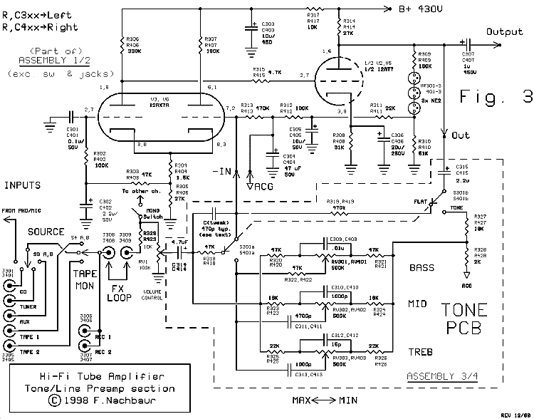
The tone-control modules are virtually identical (see Figure 3), except for a couple minor
component changes and different feedback networks. When tone bypass is selected, the voltage
gain is set at 10 (20 dB) over the audio spectrum. In tone control mode, the gain will be
approximately the same with all three tone pots in the centre of their rotation. Varying the pots
will give up to about 12 dB of boost or cut, via the three variable T-networks. Note that the tone-
control mode is basically a unity-gain configuration (to allow equal boost and cut). We achieve the
nominal 20 dB voltage gain (=10) with a 10:1 divider at the ouput, feeding the input side of the
tone control networks.

Fig. 3: Tone Control Preamplifier
By now it may be obvious that we are using the INVERTING mode for the tone preamps. The non-
inverting input is effectively grounded for AC using a capacitor (making the schematic look
strange indeed!), and both signal and feedback are applied to the inverting input. This greatly
simplifies the design of the feedback networks. To ensure that our system phase is consistent
from input to output, the inverting mode is also used in the driver/PA section that follows.
The feedback network for the tone control stages is an outboard card that also contains the linear
500K gain control pots. This also includes the gain bypass switch, which essentially reduces the
tone control amplifier to a simple line amp with a pre-set gain of 10 (20 dB).
There is an important component marked Ctweak on the schematic. The purpose of this capacitor is
to cancel out the effective parallel capacitance of your input cabling. The proper value is best
determined experimentally. Connect a decent signal generator to the CD input, and measure the
output signal at C307 with an oscilloscope or AC voltmeter. Set the scope or meter for a full-scale
reading at 1000 Hz, then increase the input frequency until the output reaches 71% of full-scale.
Note the frequency in kilohertz (we'll call it F0); the desired capacitance in picofarads can be
found using the formula:
159000/(F0 * 47)
In the prototype, the F0 frequency was about 7.5 kHz, and the simple addition of a 470 pF
capacitor levelled it out to well beyond 30 kHz. This tweak capacitor is best installed directly on
the tone control card.
Again, we have the op-amp design model of the preamplifier to thank for this simple fix to a
problem that plagues many a tube design, often without any simple recourse.
Also on the topic of frequency response: the low-frequency response of this stage is a bit of
overkill, with a 3 dB corner well below the audible range. This can actually be a drawback, since
subsonics such as turntable rumble can result in power wastage, reducing the power available for
audible frequencies. A simple fix is to put a 0.1 uF capacitor into the "FX loop" instead of the
usual jumper cables. This rolls off the subsonics below about 30 Hertz (dependent somewhat on
volume control setting; the rolloff frequency is somewhat higher at high volume control settings,
acting almost like a simple "loudness contour").


