A LOW-COST SINGLE-ENDED TRIODE AMPLIFIER
by Fred Nachbaur, Dogstar Music ©2002
4: CONSTRUCTION AND TESTING
I went to pains to design this project around parts that are readily available. The
parts list offers suggested sources for most of the parts. The
only one that might be a challenge to find at low cost is the output transformer. I used
a transformer from Triode
Electronics, the model AA-1334 on their
other transformers page. However,
this has too high a turns ratio (about 70:1) so I took it apart and added another layer
to the secondary to bring the ratio down to 35:1. However, I can't recommend this technique
to any but the most enterprising experimenters. A reasonable substitute is the model
TO-9105-1 on the same page.
However, its turns ratio is off in the other direction; it would however work fine for
8-ohm speakers, and in fact give a bit more output power (perhaps as high as 1.5 watts).
Better distortion response would, however, be obtained using 16 ohm speakers.
If you can afford to pay a bit more, an excellent choice would be the
Hammond 125CSE. While the smaller
125ASE or 125BSE devices would also work, the 125CSE is actually cheaper! (This must be
one of those supply-and-demand things.) The nice thing about these is that you can experiment
with the primary taps to see what happens at different load impedances. The 35:1 ratio as
per this design is on the black and green wires.
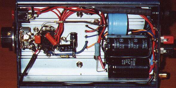
Construction of the MiniBlok SET Amplifier is relatively straightforward and non-critical, as
electronics projects go. You could take any number of approaches to the mechanical layout; as
you can tell from the pictures, I chose the "recycled" look by housing the prototype
in a blue-anodized extruded aluminum case that once housed a small DC-AC inverter. Here are a
few more ideas for you to toss around:
-
Breadboard: Mount all the major components (tube socket and transformers) on a piece of
wood plank, finished in whatever way your heart desires. The volume control and input / output
connectors can be mounted on small metal brackets. Use small brass tacks or brads as tie points
for the other components. Solid-core wire can then be routed in nice-looking squared-off runs.
-
Copper 'n' Wood: Mount the major components on a sheet of copper or brass plate, and make
a wooden frame into which the chassis-plate is recessed. This seems to be the construction method
of choice for many "art nouveau" amplifier designs these days. Incidentally, the brass
kick-plates made for door in institutional settings make for attractive, good-looking chassis
stock.
-
Conventional Chassis: You can get pre-formed chassis in either aluminum or steel, painted
or plain, from Hammond. Boring? Well, maybe. But sometimes
boring is good! ;-)
-
Funky: In the kitchen there's Tupperware™, aluminum cake-pans, skillets, even
Melmac®! In the bedroom there are jewellery boxes (but if scouting for chassis in either of
these places, be absolutely certain you get your mom / wife / GF's permission first!). In
the garage there are cedar shingles, abandoned or broken appliances like yogurt makers, toasters,
and ..er.. maybe even burned out DC-AC inverters.
-
Exotic: There are plexiglas sheets and tubing; there's PVC, aluminum or chromed brass pipes;
there are fancy woods and other materials like soapstone or high-refraction lead glass. Go nuts!
I'm going to assume at this point that you're reasonably skilled at soldering, since this is an
ability that is best learned by doing (preferably with the assistance of a coach) I'm not about to
try explaining this in a web-based article. If you're completely green in this respect, I'd
suggest enlisting the aid of a local amateur radio operator, electronics store employee, or
repair technician. Bribes are usually gladly accepted [wink]!
Be careful about wiring, especially in the comparatively high-voltage plate
circuits. If you're unsure about how the tube connections are numbered, click
here (use your browser's Back button to return to this page
afterwards.) Be sure to use capacitors rated at the specified (or higher) voltage
rating. I suggest staying away from "carbon composition" type resistors, especially
for R2; otherwise you can get another classic tube sound - lots of hiss. That being
said, if you want to use carbon-comp resistors for authenticity's sake, try to find the later
Allen-Bradley ones; these will have a smooth finish and sharp, square edges (as opposed to the
older and cheaper ones with rather rounded corners and a dull look; these can be awful as
regards tolerance and noise).
A word about grounding: The ground symbols (three horizontal lines suggesting a downward-pointing
arrow) indicate a connection to a common grounding point, which is in turn the only connection
to the chassis (if using a metal chassis). This common point should normally be the ground end of
the input jack. Since this is a relatively low-gain system, grounding isn't especially critical;
so you could cheat and use, for instance, the ground lugs on your tube socket (if available) for
tying components such as R3, C8, and tube socket pin 3 to chassis ground. The important thing is
to avoid voltage drops caused by the high inrush current into the B+ filter caps (C1 - C3) from
getting into your audio; therefore be sure that D2, C2 and C3 are connected together, with a wire
connected to their common point at one end, and to the common ground point at the other.
Some more comments on the power supply: The MiniBlok uses two separate power transformers; the
first is rated 12.6 volts at 2 amperes, and the second at 12.6 volts at 1 ampere. There is no
reason you couldn't use two identical (2 ampere) transformers; you'll end up with a slightly
higher B+ voltage if you do, which might marginally increase your available output power. Note
when wiring up the power supply that transformer T2 (the high-voltage step-up transformer) is
wired backwards; what used to be its primary is actually our secondary winding.
Modifications for 240 volt supply:
It is entirely possible to build a MiniBlok for use with 240 VAC, 50- or 60- Hz. power.
Transformers T1 and T2 will be 240V to 12.6V transformers, rated at 2A and 1A (minimum)
respectively. However, since the output of T2 will be on the order of 220 volts already,
the voltage doubler for the B+ supply is un-necessary. Diodes D1 and D2 are therefore
replaced by a 1A, 600 volt (or higher) "full-wave bridge" module (or four
discrete diodes, if you prefer). Capacitors C1 and C2 are replaced by a single 220
µF, 350V unit. Other than that, everything else remains the same.
Wiring and Testing
I recommend testing (and debugging, if necessary) the power supply first. Be very careful about
diode and capacitor polarities! The diodes have a band at the cathode end (this is the end that
corresponds to the "bar" in the schematic symbol). The capacitors will usually be marked
at the negative end with a bar or line consisting of a row of "-" symbols. At the
low-voltage filament supply output on the tube socket's pins 7 and 8 (no load) you'll typically
read about 13 volts AC. At the bias output you should read about -36 volts. At the high-voltage
output you'll read about 300 volts under no-load conditions. Be careful about accidental shorts;
these can make the Magic Smoke come out of your transformers or other components, and render them
useless. If you chose to install the optional LEDs, you should see the green LED (D5) light up when
power is on. The red one (D7) should only flash briefly while the capacitors charge, then extinguish.
IMPORTANT:
The high-voltage filter capacitors will hold a charge for a long time after
power-off, with no tube installed. To avoid an unpleasant surprise as you're working on this or
any tube circuit, discharge the high voltage capacitors after turning off the unit and
unplugging it from the wall socket. The best way to do this is to clip-lead a 10K resistor between
the positive and negative terminals of the power supply (the terminals of C3 in this case), and
leave it on for at least 30 seconds before proceeding with your work. (Don't forget to unclip it
before applying power again!)
Wire up the rest of the circuit. Be careful that every connection is correct as you're making it.
While in this relatively simple circuit it is quite easy to go back and fix errors later, it's
good to err on on the fastidious side to save yourself possible trouble (and time wasted
debugging) later on. Don't even think about plugging the tube into its socket just yet, though!
Do the following final tests:
- With the unit not plugged into the wall outlet, and after being sure the filter
capacitors are discharged, connect the negative lead of your ohm-meter to common ground, and
make the following measurements:
- Tube socket pin 7: zero ohms
- Tube socket pin 8: very near to zero ohms (may read zero on your meter)
- Tube socket pin 3: zero ohms
- Tube socket pin 6: about 820 ohms
- Tube socket pin 4: zero to 100k, as volume control turned from zero to maximum.
- Switch your meter from ohms to the highest DC voltage range (leave the negative lead connected
to the common ground point), plug in the amplifier, and turn it on. Note that the tube is not
yet plugged into the socket. Make the following voltage readings:
- Tube socket pin 1: at least -30 volts (may be higher, depending on your voltmeter's
input resistance)
- Tube socket pin 2: about 300 - 320 volts
- Tube socket pin 3: zero volts
- Tube socket pin 4: zero volts
- Tube socket pin 5: about 300 - 320 volts
- Tube socket pin 6: zero volts
- Switch your meter to a 20 volt or higher AC voltage range (leave the negative lead connected
to the common ground point). Make the following voltage readings:
- Tube socket pin 7: zero volts
- Tube socket pin 8: about 13 volts
- Turn off the amp, and plug in the tube. Connect a 4 to 10 ohm dummy load resistor to the
speaker terminals. Switch your meter back to the highest DC voltage range (leave the negative
lead connected to the common ground point), and turn the amplifier back on. Make the following
voltage readings:
- Tube socket pin 1: at least -30 volts (may be higher, depending on your voltmeter's
input resistance)
- Tube socket pin 2: about 200 - 220 volts
- Tube socket pin 3: zero volts
- Tube socket pin 4: zero volts
- Tube socket pin 5: about 130 - 150 volts
- Tube socket pin 6: about 1.5 volts (you may have to switch to a lower range)
Everything ok? Great! Turn the amp off, button it up, disconnect the dummy load resistor and
connect your speaker in its place. Connect your input source, turn on the amp, and enjoy!