A HIGH-PRECISION TUBE PHONO PREAMPLIFIER
by Fred Nachbaur, Dogstar Music ©1998, 2000
3B: OTHER APPLICATIONS FOR THE UNIVERSAL PREAMP MODULE
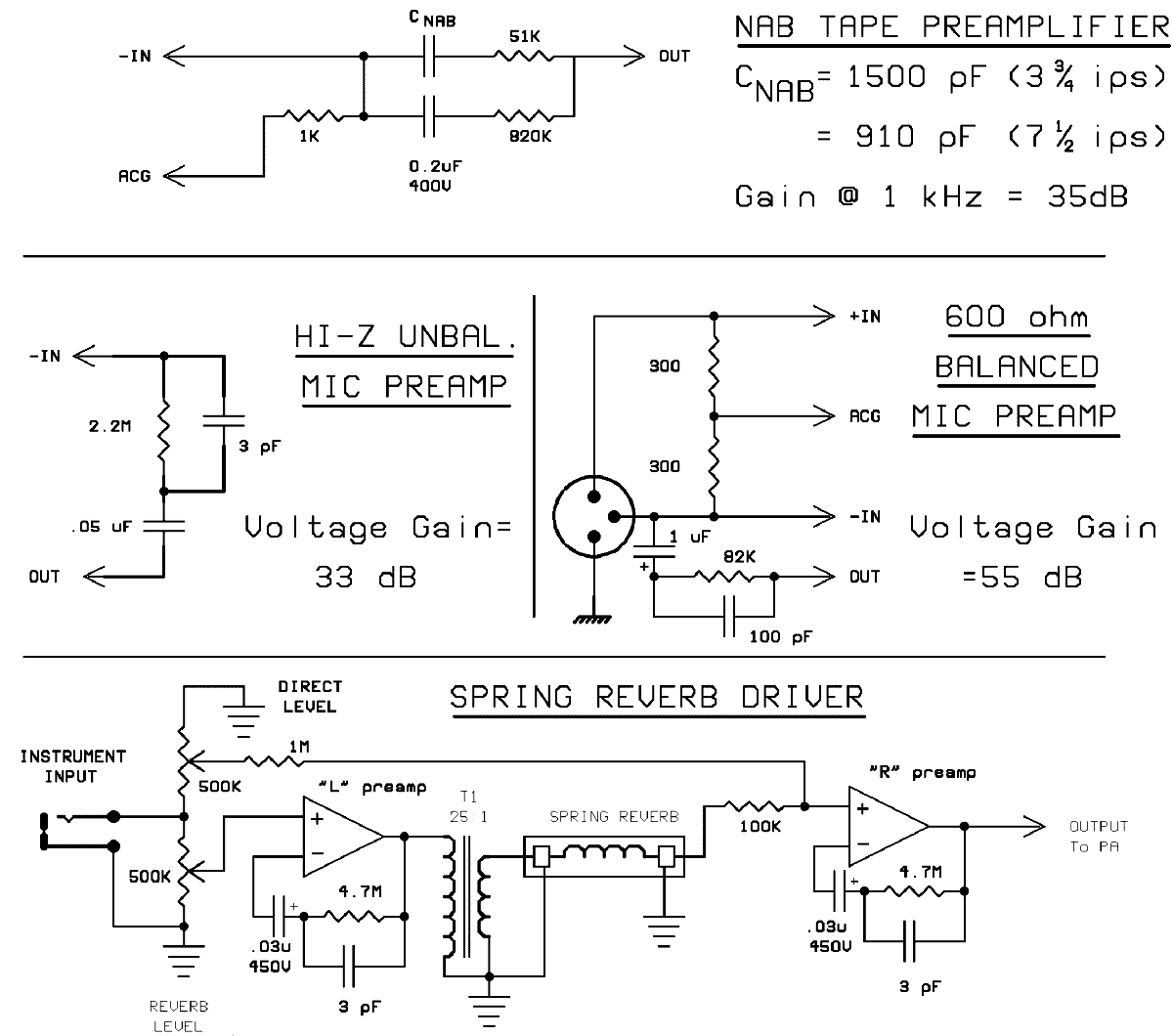
Figure 8 shows a few other options for the basic preamp circuit. This was originally intended as an
Appendix, but it's sufficiently important to be included in this discussion of the "Quasi-opamp
Tube Preamp." You could design any number of stand-alone applications for this device, the ones
provided here are just a few examples of the possibilities.

Fig. 8: Other Applications for the Preamp Module
You might have an old reel-to-reel in a closet somewhere. If not, keep an eye out at the second-
hand stores; these can often be picked up for a song. The biggest drawback with many of these is
the early transistor playback preamps, especially the ones that use germanium transistors.
Replace the playback amp with the variation shown in Fig. 8a. Note that for proper equalization at
both speeds (3-3/4 and 7-1/2 ips) you'll need to switch between two different values for CNAB.
The NAB tape standard is even simpler than the RIAA phono spec, consisting essentially of a 6 dB
per octave de-emphasis. Again, we use the preamp in open-loop mode at low bass frequencies,
and again we use a low value of Ri to maximize our bass response.
Fig. 8b shows a preamp for high-impedance, single-ended dynamic microphones. It is similar to
our Mic/Line mode, except that the fixed gain simplifies construction for standalone projects. Add
an impedance-matching transformer, and the circuit is usable with low-impedance microphones.
Fig. 8c shows a application of the differential input capability of our preamp. This is for balanced,
low impedance microphones. Note that this is a transformer-less circuit, and therefore offers a
significant improvement over Fig. 8b. However, the circuit's shortcomings should be pointed out:
First, as mentioned earlier, the common-mode rejection ratio of this circuit is nothing to write
home about, and so it will not be suitable if your microphone is connected via a long cable run
near stage lighting cables, etc. Secondly, the microphone element will be sitting at about 25 volts
DC relative to system ground. A dedicated balanced mic tube preamp that avoids these
shortcomings would not be difficult to design, I'd consider taking on such a project if the interest
is there.
Finally, Fig. 8d shows a "spring reverb" driver. The transformer can be a small output
transformer, such as might be salvaged from an old tube radio. A turns ratio of about 25:1
(corresponding to an impedance ratio of 5000 ohms to 8 ohms or thereabouts) would be fine. The
first preamplifier (e.g. "left") amplifies your instrument's output with enough drive to run the
reverb input transducer via the matching transformer. The second preamplifier (e.g. "right")
amplifies the much lower voltage appearing at the reverb's output transducer. Separate gain
controls allow you to mix "dry" and "reverb" signals to your heart's content. The resistor values
are given as a starting point; depending on the instrument and your particular spring reverb
assembly, you might have to trim values to suit. As shown, there should be enough gain to allow
you to distort either signal by overdriving the preamp sections.
Incidentally, because of the unique DC feedback system, the clipping characteristics of this circuit
are quite a bit different than what you might be used to, even compared to other tube circuits.
The author has not experimented with the fine points of this, so the field is ripe for
experimentation in this area.
A trippy view of the Preamp PCB layout
END OF ARTICLE