 |
DIS*PLAYER V2.11
General Information
|
|
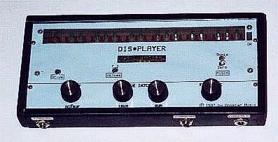 |
| Prototype for the Electronics Now article, set up as a standalone unit |
| Document |
Hi-resolution (Printable) |
Low-resolution (Fax quality) |
Rich Text Format |
| Parts List | N/A | N/A | disparts.rtf |
| Schematic diagram | dis_schl.gif | dis_schm.gif | N/A |
| PCB Wiring side | pcb_wire.gif | pcb_wi-m.gif | N/A |
| PCB Component side | pcb_comp.gif | pcb_co-m.gif | N/A |
| PCB Silkscreen layout | pcb_silk.gif | pcb_si-m.gif | N/A |
| Octavizer schematic | tmax-f2l.gif | tmax-f2s.gif | N/A |
| Low note: A=110 | ||
| C1, C2, C6, C12-C19 | 2.2 µF 16V tantalum | |
| C3 | 3300 pF ceramic | |
| C4 | 4.7 µF 16V electrolytic | |
| C5 | 10 µF 16V electrolytic | |
| C7 | C20, C21 - 0.01 µF disc ceramic | |
| C8 | 0.02 µF mylar, 5% | (0.01 µF) |
| C9 | 0.47 µF 16V electrolytic or tantalum | (0.22 µF) |
| C10, C22 | 0.10 µF mylar or ceramic | (0.05 µF) |
| C11 | 0.20 µF mylar or ceramic | (0.10 µF) |
| C23 | 1000 pF ceramic | |
| C24 | 470 pF ceramic |
| D1, D2 | 1N4148, 1N914 or equivalent |
| IC1 | 7805 positive regulator, TO220 |
| IC2 | NE555 or TLC555 timer |
| IC3 | LM311N comparator |
| IC4 | DM4027 or MC14027 dual J-K flipflop |
| IC5 | LM2917N F-V converter (14-pin version) |
| IC6 | LF353, TL062, or TL082 dual op amp, FET input |
| IC6-IC11 | LM3914 LED linear display drivers |
| IC12 | 79L05 negative regulator, TO92 |
| J1 | Hollow pin jack, 2.1 mm. |
| J2, J3 | 1/4 mono phone jack |
| LED1-LED3 | small green LEDs |
| LED4-LED6 | small yellow or orange LEDs |
| LED7-LED10 | small red LEDs |
| LED11, 13, 14, 16, 18, 19, 21, 23, 25, 26, 28, 30, 31, 33, 35, 37, 38, 40, 42, 43, 45, 47. and 49 | large red LEDs |
| LED12, 15, 17, 20, 22, 24, 27, 29, 32. 34, 36, 39, 41, 44, 46, and 48 | large green LEDs |
| LED 50 (optional) | large orange or yellow LED |
| Q1,Q2 | 2N3904. 2N4401, 2N2222 or similar NPN signal transistors (from same production run) |
| R1 | 24K (K=1000; i.e. 24K = 24000 ohms) |
| R2 | 56K |
| R3, R39 | 22K |
| R4, R5, R8, R9 ,R12 ,R13 ,R19 | 100K |
| R14, R17 | 4.7K |
| R7 | 68K |
| R6, R10, R24, R27, R30, R33-R37 | 10K |
| R11 | 470 ohm |
| R15, R18 | 47K |
| R16 | 1K |
| R20 | 390K |
| R21 | 750 ohm |
| R22, R25, R28, R31 | 20K |
| R23 | 1.5K |
| R26 | 2.2K |
| R29, R32 | 3K |
| R38 | 82K |
| R40 | 4.7 Megohm |
| RV1-RV4 | 50K linear trimpots (layout is for Bourns 3329-H-1-503 or equivalent) |
| SW1 | 2-pole, 3-position rotary switch (or 3-pole, 4-position for power switching) |
| SW2 (optional) | SPST power on-off switch |
| single- or double-sided PC board |
| jumper wire (single-sided board) or feedthrough wire (double-sided board) |
| mounting hardware |
| case |
| hookup wire |
| 12 volt DC, 200 mA. (or better) power supply |
| cables to instrument |
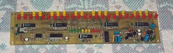 |
| Fully assembled Dis*Player board |
 |
| Wiring side of bare PCB |