DIS*PLAYER V2.11
Theory and Construction
Important notice: This project is suitable for intermediate to advanced electronics hobbyists.
If you are a beginner, or if the material looks difficult, I recommend enlisting the help of
an experienced PC-board maker / project builder. While I'll do my best to answer valid questions,
I cannot provide extensive free tech support; especially if the answers to your questions are
covered in the pages on this site. This page is the full documentation for the Dis*Player project.
If you built "Theremax" (Electronics Now, Feb. 1996) and gave up on
trying to get musical sounds out of this remarkable instrument, don't
despair. DIS*PLAYER to the rescue!
This device gives visual feedback of which note you're playing, so you
can set up the note before bringing up the volume to sound it. It
features a 40-LED display, for over three octaves of range at any given
time. Furthermore, a three-position switch extends the range by two
octaves, for a total usable range of over five octaves. You'll be amazed
at how quickly you'll pick out recognizable tunes with DIS*PLAYER's
help.
The usefulness of DIS*PLAYER is not limited to the Theremax or other
theremin design. Use it with anything that lacks frets, keys or valves:
bowed string instruments, fretless bass, trombones and slide whistles,
even vocals. DIS*PLAYER's usefulness is limited only by your
imagination.
As a bonus, DIS*PLAYER includes a "volume" display section (VU meter).
Again, this feature was spawned by "dis player's" need to have visual
feedback of volume setting on the Theremax.
The theory of operation is given first, and I recommend that you read it through
at least once before getting on with the construction. However, if you'd prefer
to bypass the "How It Works" section,
Click Here to jump right to the construction section.
All the resources needed for building this project are provided in a separate
Resources page, including a parts list and
high-resolution printable versions of the board artwork, schematic, and silk-screen
artwork.
How It Works
1) TONE DISPLAY
The heart of the circuit is the tone (pitch) display section, based on
the popular LM3914 display driver. This device drives ten LEDs in a
linear display, with programmable endpoints and the choice of "dot" or
"bar" modes of operation. Furthermore, it is possible to "chain"
multiple devices for displays of virtually unlimited size.
IC 7 through IC 10 are wired in a "minimum parts" chained configuration
in dot mode. This mode is easier to read in our particular application,
and also places less demands on our power supply. LED current is
programmed at about 20 milliamps, giving a bright, easy to read display.
LEDs 11 through 49 (or optionally 50) are arranged in a keyboard pattern
to make notes easily recognizable to anyone with piano or keyboard
experience. Red LEDs represent the white keys, and green LEDs represent
the black keys of a piano. The lowest note is an "A", and the highest
note is a "C" a bit over three octaves higher. This last LED is
optional, because it remains lit when the maximum pitch it represents is
exceeded. If you prefer the display to go blank when out of range, omit
this LED. Otherwise, wire it to the otherwise unused pin 10 of IC-10. If
you do use it, I suggest using another color (e.g. orange) to indicate
that the pitch it displays isn't necessarily correct.
Resistors across the first and ninth LED of each driver reduce or
eliminate the dim glow that these LEDs emit, due to small currents that
pass through them. These currents are a by-product of the way the LM391x
family of devices implements dot-mode "chaining." If you aren't bothered
with this dim glow, these resistors (R22, R24, R25, R27,
R28, R30, R31 and R33) can be omitted.
The resistors from pin 6-7 of each device to ground program the LED
currents. Note that they are not the same value; this is because the
reference voltage of each successive driver is 1.25 volts higher than
the previous one.
The inputs of the LM3914's are tied together, resulting in a continuous
linear display with a full-scale voltage of about 5 volts.
One quirk of the LM391x family of display drivers is that they need to
be well bypassed on both the LED supply and the main supply lines.
That's why there are all those 2.2 µF tantalum capacitors along the LED
supply rail, and on each LM3914's pin 3. You might try omitting some or
all of them; you just might get lucky. But if you do omit them and get
bizarre displays due to oscillations, don't say you weren't warned.
At this point we should note that the notes we are displaying represent
a logarithmic scale, In other words, each time we double the frequency
(go up an octave), the control voltage to our display section should
increase by a fixed amount (about 1.5 volts in practise). So how does a
(logarithmic) frequency input get converted into the linear equivalent
for display on our "visual keyboard?" For the answer we have to go to
the opposite end of the circuit.
The incoming frequency signal is applied to IC-3, an LM311 comparator,
which converts it into a square wave with the proper levels to reliably
drive the octave dividers that follow. Drive trimmer RV1 sets the amount
of signal applied to the comparator. This helps to assure that we have
enough signal for reliable operation across the usable range, while
minimizing the display of "birdies" or other noise. Resistors R4 and R5
set the toggle point of the comparator at 1/2 supply, and R3 forms the
load for the LM311's open-collector output.
From there the signal passes through two frequency-divider stages,
comprised of the two sections of a dual J-K flip-flop (IC-4, a 4027 CMOS
chip). This gives us a choice of three octave ranges, selected by one of
the poles of switch SW1. The other pole of the switch is used to sink a
low current through one of three LEDs representing "C" on the keyboard,
to mark "middle C" (or "high C") for any of the octave switch settings
by making that LED glow dimly.
From there we go to the "frequency-to-voltage" converter IC-5, an LM2917
(14-pin version). You may wonder why we didn't simply use the Pitch CV
output from the Theremax. Good point. The answer is three-fold; first,
not everyone will be using DIS*PLAYER with this theremin design; having
an onboard F-V converter makes the design more universally applicable.
Secondly, the Pitch CV output on Theremax is not nearly as linear as a
dedicated F-V like the LM2917. Finally, the LM2917 has a built-in op amp
which can be used for active filtration of ripple, a necessity to
properly display the lower frequencies. Without ripple filtering, more
than one light would be illuminated in the lower ranges.
Resistors R12 and R13 set the LM2914's reference at 1/2 supply. R11 is a
load for the built-in zener diode in the chip, stabilizing it against
variations of supply voltage. Capacitor C8 and resistor R7 program the
chip's frequency-to-voltage range, chosen to give the full-scale voltage
of about 6.5 volts when input frequency is 550 Hz. (or 1100 Hz. in the
higher octave variant). R8, R9, C10 and C11 form a two-pole Butterworth
filter, to greatly reduce ripple before passing to the unity-gain (for
DC) op-amp section. This is why we use the 14-pin version of the LM2917,
since the 8-pin variant doesn't allow us to tap into the input of the op
amp section. Finally, R10 forms the load for the LM2917's open-emitter
output.
The values shown in the schematic are for a minimum frequency of 55 Hz.
(A-3) and maximum (with the octave switch in the third position) is 2093
Hz. (C3) The bottom end is a pretty low bass note, so you might prefer
(as I do) to start the display an octave higher. In this case, use the
alternate capacitor values in the parts list (C8 = .01 µF, C9 = 0.22 µF,
C10 = 0.05 µF, and C11 = 0.1 µF). With the alternate values, minimum
frequency is 110 Hz. (A-2) and maximum frequency is 4186 Hz. (C4).
So now we have a voltage which is a highly linear analog of the incoming
frequency. How do we take the logarithm of this voltage for proper
display on our visual keyboard?
The key to the answer is the fact that the voltage across a transistor
with its base and collector tied together is proportional to the
logarithm of the current passing through it. In practise, this means
that the collector/base to emitter voltage increases by about 17
millivolts for every doubling of current (representing one octave).
The first section of a dual JFET op-amp (IC-6) makes use of this fact.
To briefly review op-amp theory, an ideal op amp will have zero volts
across its differential inputs (infinite voltage gain), and an infinite
input resistance (zero input bias current). Fortunately, the JFET op amp
we're using approaches this ideal very closely. This means that in the
inverting amplifier configuration, the current through the "feedback
element" (Q1, a transistor with base and collector tied together in our
case) equals the current in the "input element" (R15 in our case).
Furthermore, the current in the input element will be directly
proportional to the applied voltage. Tying this all together, what we
see at the output is a voltage proportional to the logarithm of the
input voltage.
In passing, I should note why it is important that this op-amp be a
JFET-input device. When doing linear-to-log conversions, even tiny input
bias currents (50 nanoamperes in the case of the common LM358) are
enough to mess up our linearity. The LF353/TL062 type of devices
typically have input currents three orders of magnitude less (50
picoamps!!), and are far better suited to our needs.
You'll note that the logarithmic output voltage is inverted - i.e.
negative-going. Not to worry, the second section of the dual op-amp IC-6
takes care of that by inverting it again. This section also sets our
gain (slope) via RV4 in its feedback element, and our zero offset
(y-intercept) via RV3 in its input element. We would have needed a
scaling amplifier anyway, to bring the 17 mV per octave log amp signal
to the required 1.5 volts per octave. Making both stages inverters
eliminates complications that result from trying to make a non-inverting
log amp.
IC-6b performs another very important job; temperature compensation.
Another interesting property of the transistor with base and collector
tied together is that, at a given current, the voltage across it is a
pretty linear representation of temperature. This feature is useful for
any number of temperature measuring applications, but a real drawback
for log amps.
So this is why Q2 was included in the biasing network for IC-6b. A
temperature induced voltage change in Q1 will (presumably) cause the
same amount of change in Q2. The circuit is wired in such a way that the
effects of these voltage changes cancel. This is why we choose two
transistors from the same production run. You might ask why we don't use
a dual transistor (two transistors on the same die) - good point. The
answer has more to do with cost and availability than any technical
reason. Experiments have shown that the resulting temperature stability
improvement using a dual transistor is not enough to warrant the
additional trouble. If you're really concerned about this, you can of
course use a dual transistor package, or simply use discrete
transistors, leaving the leads long enough so they can be bent into
physical contact with each other. A dab of thermal compound and a tiny
elastic band to strap them together will give virtually the same degree
of stability as a dual transistor.
Capacitor C21 eliminates any residual ripple, or other high-frequency
noise picked up along the way. The output from IC6-b passes through
summing resistor R36 (the need for which will be explained shortly) to
the inputs of the display driver ICs (pins 5), and the display section
is complete.
3) POWER SUPPLY
As mentioned earlier, the F-V converter has its own built-in zener
supply, so any supply voltage in the range of 10 - 14 volts will be
adequate. Similarly, the other ICs' requirements are quite forgiving.
The exception is the Log amp / Scaling amp section (IC-6). While it
doesn't really care about its supply voltage, the biasing network
(including the temperature compensator Q2) needs to have well-regulated
voltage. This is one reason for the use of 5-volt positive regulator
IC-1. Again, using a 2.2 µF tantalum at its output prevents possible
oscillations that could ruin your day.
This regulator also supplies the LED current for the display drivers.
Running the LED supply on a lower voltage greatly reduces the heating on
the display driver ICs.
The next item is that funny little circuit built around IC-2, a common
NE555 (or its CMOS equivalent TLC555) timer IC. This is the heart of our
negative supply inverter. Rather than requiring you to come up with a
bipolar supply, and because the maximum demand on the negative supply
for IC-6 is only a couple milliamps, I included this little circuit for
your convenience. Of course, if you already have a source of -5V, you
can omit this entire section (including IC-12). And yes, I realize that
there are dedicated ICs available for this purpose, but again it may not
be readily available at your local parts jobber. Whereas you probably
already have everything you need to build the 555 version in your junk
box.
IC-2 operates in a variant of the astable multivibrator circuit,
optimized for as near to a 50% duty cycle as is practical. Resistors R1
and R2, and capacitor C3 set the frequency of oscillation at about 3.8
kHz. The resulting square wave is clamped by C4 and D1, rectified by D2
and filtered by C5. (Note that the circuit consisting of C4, C5 and the
two diodes is nothing more than the classic "voltage doubler" circuit!
In effect, we're "doubling" the peak value of the square wave, relative
to its average level. Result - a negative voltage approximately equal to
the original positive supply voltage.) The result is a negative DC
voltage, albeit with poor regulation.
This last drawback is fixed by IC-12, a little 5 volt negative
regulator. If you don't have or can't find the 79L05 (TO-92 version),
there's no reason why you can't squeeze the more common 7905 (TO-220
package) into the layout.
While we have a nice clean, constant frequency square wave available,
let's add another refinement: a "fine tuning" indication. As our display
section stands so far, we could be off by almost a quarter-tone with any
given LED illuminated. We can greatly improve this by superimposing a
low-level (about 80 millivolt) triangle wave on top of our DC signal to
the display drivers. This will cause a single lamp to light only if
we're pretty close to being "on pitch," since each LED represents a 125
millivolt increase. If we're even a little off pitch, the next light up
or down will start lighting, giving an "overlap" effect much like some
chromatic tuners. If you prefer a sharp transition between notes,
setting exact pitch by ear instead of by watching the LEDs, you can omit
this section of the circuit.
It might seem odd that we'd want to add ripple to our display after all
the trouble we went to getting rid of ripple generated by the F-V
converter. The difference is that with a fixed frequency source like our
555 oscillator, the ripple amplitude will be constant and predictable.
The 3.8 kHz. square wave from IC2 is integrated into a reasonable
approximation of a triangle wave by R37 and C22, and injected to the
inputs of the display drivers via the voltage divider formed by R38 and
R36. Capacitor C23 provides DC isolation so that our fine-tuning circuit
does not affect the DC level coming out of our scaling amplifier IC6-b.
2) VOLUME DISPLAY
After all that, the volume display section is almost trivial. Again, we
use an LM3914 (IC-11) and ten light-emitting diodes (LED1-10).
This time, though, we don't
have to bother with log amps and such, because the Volume CV voltage
supplied by Theremax is already a logarithmic analog of output volume,
due to the design of the unit's VCA! So all it takes is a scaling pot
RV2, a little bypass capacitor C20 (just for good measure), and away we
go.
You might prefer a "bar" display for this feature. If so, tie pin 9
("mode select") to pin 3 (12 volt supply) instead of to pin 11 (cathode
of LED-9) as shown.
If you're using DIS*PLAYER with something other than Theremax, you may
need to replace IC-11 with its logarithmic sibling the LM3915. This
gives a display in 3 dB steps, rather than the linear display of the
LM3914. Incidentally, you don't even need to rectify and filter your
incoming audio source; the LM3915 works fine straight from a line-level
input with a maximum peak voltage of 1.25 volts or greater. Use dot mode
as shown, and you'll get a cool "quasi-bar" display that shows peak
values and also suggests the average value.
Incidentally, if you're wondering why we didn't just use LM3915's in the
tone display section, it's because the logarithmic steps are fixed at 3
dB. (about 41% increase per step) rather than the approximately 4%
increase per step needed to display half-tones.
Building Dis*Player
1) CONSTRUCTION
If you are a relatively advanced electronics experimenter, you could build DIS*PLAYER on a piece
of perf-board, about 3 x 10", using point-to-point wiring. However, for best results, easiest
construction, and the tidiest final result I recommend either making or buying a PC board.
(Pre-etched, drilled and silk-screened boards are available from Dogstar Music at reasonable
cost. Click Here for details).
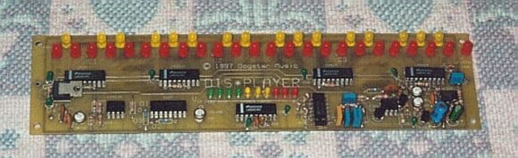
If you use perfboard, try to follow the layout of the printed circuit board shown
below. While the exact layout isn't critical, you'll find it easiest to wire up the project
using this layout, which has been optimised with regards to component location.
If you make your own board, you have a choice of single- or
double-sided. Artwork for both sides of the board, as well as (optional)
silk-screen artwork, are available for downloading from the
Dis*Player Resources page. You can
photocopy the silk-screen print onto clear mylar, and use it as an
overlay for your board for that professional look. After drilling the
board, line up the overlay and use an awl or similar tool to poke holes
through it for your components.
If you use a single-sided board, you'll have to run jumper wires
corresponding to the traces on the "component-side" artwork.
Note that the +12V and ground rails for the LM3914 tone display drivers pass
UNDER the ICs, so you'll have to run the jumpers before installing the chips.
Stretch them tight before soldering to prevent them from shorting against each other,
or against one or more of the IC legs. Extra pad holes are provided on
either side of the little bypass capacitors for your jumpers.
If you use a double-sided board, you'll have to run little feed-through
wires at the ends of the traces on the component side. You don't have to
drill out the pads on either side of the bypass capacitors; instead,
simply use the capacitors as feedthroughs by soldering their leads on
both sides.
Install the rest of the components, referring to the schematic and/or
the silkscreen layout. Install the 4027 chip (IC-4) last, since it's the
only component that is somewhat static sensitive (unless you opted for a
CMOS version of the 555 timer, in which case you want to defer soldering
it in until last). As usual, be careful about proper IC and transistor
orientation, diode and capacitor polarity where applicable, and LED
polarity. The shorter lead on LEDs is generally the cathode (negative
side), but for good measure check for the little flat spot on the
flanged part of the LED; this flat spot is the cathode, and goes towards
the driver ICs. If you opt to install the last LED (LED50), solder it
into the holes indicated and run short jumper wires to the +5V rail and
to pin 10 of IC 10.
You also need to decide whether you want the lower range (starting at
A=55 Hz.) or the higher one (starting at A=110 Hz.) Unless you're really
into low bass, I recommend using the alternate values (shown in
parentheses on the schematic and parts list). This is especially true if
you are using DIS*PLAYER with Theremax or other theremin design; the low
range of most theremins is quite unstable unless you take great pains to
shield the oscillators from each other.
Mount the board to a piece of 1/4" clear acrylic lucite ("Plexiglas",
etc.) 3" x 10", with suitable holes drilled for mounting and for the
potentiometer adjustments. This can be, in turn, mounted on a box or
frame made from strips of wood or similar material.
Make arrangements for a suitable source of +12V DC power. A 12 volt, 200
mA "wall-wart" power supply is okay, but a 500 mA unit with a 7812
regulator (to reduce ripple) is preferred. If you're using DIS*PLAYER
with Theremax, you'll be pushing it if you try to run both units from
the same wall supply; either get a second supply for DIS*PLAYER, or
upgrade to a 500 mA unit to power both.
If you wish, you can add an SPST toggle or slide switch as a "power"
switch, in series with the positive terminal of the power supply, or use
a four position 3-pole switch for SW1. Use the third pole for power switching,
with all but the first (off) position strapped together such that power is applied
whenever one of the three octave settings is selected.
You'll also need to make arrangements to bring in the Volume CV voltage
and the constant-amplitude frequency signal. Ordinary mono 1/4" phone
jacks are probably the best bet unless you opted (as I did) to include DIS*PLAYER in the
same enclosure with your Theremax.
The Volume CV input plugs right into the corresponding jack on Theremax,
but you'll have to add a jack to Theremax to bring out the
constant-amplitude frequency signal. You can take this from pin 2 of
Theremax's IC2, with a 470K resistor in series. (Without the resistor,
adjusting your DRIVE control gets very touchy). The advantage to this is
that the signal is already a square-wave. The disadvantage is that there
is little or no suppression of the odd signals you can get when the
pitch oscillators are close to locking.
I prefer to take the signal from the output of the pitch buffer amp,
i.e. the collector of Q8. This point has the added advantage of being
usable as a "monitor" output, for feeding into a small local amplifier
(via a coupling capacitor) so you can make fine adjustments to your
pitch before bringing up the volume and sending the note out to the main
amplifier.
For now, don't bother with the octave switch. Preliminary testing can be
done by running a jumper lead from the point marked Sin (pin 1 of IC-5)
to the point marked O3 (pin 7 of IC-3).
Check over your work, do some continuity checks with your ohm-meter to
insure that you don't have, for instance, direct shorts between supply
and ground, and double check all polarities and orientations. Look for
cold solder joints, solder bridges, and wrong values. When you're
satisfied that everything looks okay, get set up for testing and
adjustment.
2) TESTING AND ADJUSTMENT
Set all trimmer pots to approximately the center of adjustment. Apply a
signal generator (waveform and amplitude don't matter much) to the
frequency input. Unless you have an accurately calibrated signal
generator, you'll also want to put a frequency counter in parallel with
the input.
Alternately, connect a synth or other keyboard instrument to the
frequency input, and select the "cleanest" sound you have; i.e. no
effects, harmonics or after-touch dynamics. A clean "flute" sound or
something on that order would be perfect.
You may or may not see any lights at this point. However, if you vary
the frequency generator through its lower range, or play your instrument
across its range, you should somewhere or other see the pitch-display
come to life. Try increasing your drive adjustment and/or your generator
output. If you still don't get any action, backtrack and find your
problem. Follow through the "How It Works" section, preferably with an
oscilloscope, to see where you're losing your signal. Check the output
of IC-5 (pin 5 or 10) with a DC voltmeter; you should get a varying
voltage between zero and about 6.5 volts as you sweep through the
frequency range (0 - 550 Hz. or 0 - 1100 Hz).
Assuming that all is well so far, adjust the DRIVE control just beyond
the point where the display stabilizes when you play a note or apply the
signal generator. If you turn it too high, you might get funny displays
due to harmonics or background noise.
Now play an A-3 or set your signal generator to 55 Hz. (or A-2 = 110 Hz
if you used the alternate octave component values). Adjust the ZERO pot
until the first light (low A) comes on. Now set your generator to 440
Hz. (or play an A0, the next A above middle C) if you used the low-band
component values, or 880 Hz (A1) if you used the higher version. Adjust
the SCALE pot until the high A lights (LED 47). Repeat these two
adjustments a few times; they should quickly converge.
Now hook up the octave switch for the final test. I suggest using shielded wire
for the pole that does the octave switching (O1, O2, O3 and Sin), since
these points carry high-level square waves that could get into places
you really don't want them. Ground the shield only at the PC board end.
As you flip the switch, you should see the appropriate "C" LED light
dimly to indicate your reference point ("middle C" for the low-octave
version, or "high C" for the higher version). The note display should
track correspondingly.
The volume display is the easy part. Play your Theremax (or other
instrument) at maximum volume, and adjust the VOLUME SCALE pot until the
last light is lit. Voila.
For fun, you can check the operation of the temperature compensating
circuit. With a constant frequency being displayed, briefly touch your
soldering iron to the case of Q1. You'll see the frequency display
rapidly change as the transistor warms up even slightly. Now warm up Q2;
you'll see the same change, but in the opposite direction.
Finish assembly, and recheck your adjustments. If you chose to omit the
ripple-injection "fine tuning" option and want to get as accurate as
possible, try adjusting your ZERO and FULL SCALE adjustments
using the following frequencies:
|
LOW VERSION |
HIGH VERSION |
| ZERO |
58 Hz. |
116 Hz. |
| F-SCALE |
467 Hz. |
934 Hz. |
This represents a frequency one quarter-tone above A (i.e. midway
between A and B-flat). Alternately, adjust your keyboard instrument's
master pitch adjustment so that it's a quarter-tone high. Adjust your trimmers
so that both the A and the B-flat LEDs light up. (The adjustment will be
tricky, but you'll get a lot closer to the center of the range using
this approach.)
If you're using this with Theremax, you'll probably find weird displays
happening as you null your pitch oscillators. This is "normal", if
anything this odd-looking can be considered normal. What's happening is
those unpredictable, random and very unmusical "artifacts" as the
oscillators try to lock. This will be especially pronounced if you opted
for the low-octave components. You can reduce or eliminate this by
careful adjustment of the DRIVE control.
3) OTHER USES AND MODS
If you wish, you can add a TRANSPOSE of FINE TUNE adjustment to your
front panel by placing a linear potentiometer in series with RV3 (cut
the trace between RV3 and R18). The circuit will track well as you
transpose to different keys. Note that if you go too far afield, the
high end of the display might "bottom out" due to saturation of the F-V
converter. A 1K pot will give very fine pitch display adjustment,
allowing you to easily tune up with other instruments; a 10K pot will
give about 1/2 octave transposition in either direction. I find 5K to be
a good compromise.
You might find useful things to do with the octave outputs (at O1 and
O2). For instance, you can mix them in with the main signal from
Theremax (replace R34 and R35 with 10K log-taper pots, and wire as shown
in Figure 2) for yet another timbral option.
You could alternately run the octave outputs into separate amplifiers, preferably
controlled via a stereo mixer with tone controls, for really way-out stereo imaging.
If you want to use DIS*PLAYER for a variety of pitch-sensing purposes,
install a front-panel DRIVE control. This will make it easier to adapt
to any particular situation.
There's no reason why you couldn't experiment with 11- or 13-note
scales. Simply set up your pitch FULL SCALE adjustment to make one
octave represent 11 or 13 lights. It will be somewhat confusing because
the display will still apparently show 12 notes per octave, but the
music you produce with such scales will be so weird anyway, who cares.
Other uses: The input to the log amp can be just about anything you
want. How about a super-expanded VU meter? Sure; just disconnect R15
from the output of IC-5, and use it as a direct input to your signal
source (AC or DC). Each light will represent 0.5 dB, for a total dynamic
range of 20 dB.
How about using DIS*PLAYER as a high-resolution Photographic Light Meter? No problem. Run the
output of a silicon solar cell through a DC amplifier built around an op-amp. Each LED will
represent 1/12 of an f-stop, giving a total usable range of a little over three f-stops,
extensible to five stops using the "octave" switching option.
Happy DIS*PLAYERing!
Back to Top
Theremin Home
Dis*Player Description and Resources
Back to Fred's Freebies
To my music home page
---This page last updated Apr. 18, 2002.