Written June 2001
A VACUUM TUBE STUDIO PREAMPLIFIER
(Preliminary)
by Fred Nachbaur, Dogstar Music ©1998, 2001
1: INTRODUCTION
Two persons have recently inquired about availability of a vacuum tube preamplifier design for use
with musical instruments in a studio setting. The first was interested in a flexible preamp for use
with a high-end acoustic guitar with piezo-electric bridge pickup, and the second wanted a preamp
for use with a guitar emulator, to provide add some of the warmth that vacuum valves can provide.
Both of these requirements, and very probably many more, can be met using a variation on
The Universal Tube Preamp design. I have, in fact, used my
RA-100 Reference Amplifier for precisely such purposes; the combination of
clean, noise-free amplification and non-obtrusive tone controls makes an ideal preamplifier for
musical instruments.
However, if we're looking for a dedicated, standalone preamplifier (perhaps assembled on a rack-mountable
panel), there are a few changes we can implement to the universal preamp design in order to improve
and customise it for musical instrument applications.
2: DISCLAIMER
As of this writing, I have not actually built this variant on the Universal Preamp design, and it's
unlikely that I'll do so in the foreseeable future. I will therefore be grateful for any reports, and
would be happy to help out in the relatively unlikely event that there are significant bugs in the
design implementation as presented here. This is the main reason why I put this project into the
"advanced" category; other than the fact that there may be tweaks required, there is nothing
particularly difficult about the design or its construction.
3: SCHEMATIC
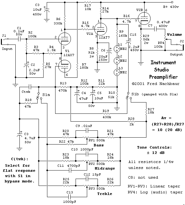
Here is the schematic of the modified preamplifier circuit, redrawn from the original to fit better
into the web format. An enlarged and dithered version, suitable for laser-printing at 300 dpi (final
size 7-1/2" x 10") is available by right-clicking / Save As...
here.
4: IMPROVEMENTS
This is essentially a revisited version of the
tone control preamp section of the RA-100, so you might want to have a look
at parts of that article for theory of operation. The significant differences are:
- The "quasi op-amp" is used in a non-inverting mode of operation, unlike the RA-100's
tone control section which used the inverting mode. The non-inverting mode is preferred for studio
use, because it maintains the original phase of the signal; you might, for instance, wish to mix
together the output from the preamp with a sample of the input signal.
The non-inverting mode also has the advantage of providing a constant impedance at the input, not
affected in any way by the tone control settings. In the RA-100 this didn't matter, since the input
was always understood to be fed from a low impedance source. In the case of a general-purpose studio
preamp, however, this cannot be assumed to always be the case.
The trade-off is that the gain calculations for non-inverting mode are slightly different from inverting
mode. To simplify (assuming that open-loop gain is much greater than closed-loop gain), with
Zf = feedback impedance and Zi = input impedance:
Inverting: Av ~ Zf/Zi
Non-inverting: Av ~ (Zf + Zi)/Zi =
Zf/Zi + 1
While this difference is not significant at higher closed-loop gains, it does come into play at lower
overall gain settings. (This is another reason why the inverting mode was used in the RA-100 tone
control circuit.) The triple-T tone control network simultaneously adjusts both input and feedback
impedance values when any of the pots are adjusted. The end effect, when non-inverting mode is used, is
to slightly reduce the amount of maximum "cut" as compared to maximum "boost".
For studio use, however, my opinion is that the advantages of fixed input impedance and phase
preservation outweigh this drawback.
-
The original circuit uses a 12AX7 differential amplifier, and half of a 12AT7 dual triode for the
output stage for each channel of a stereo system. This means that, in a monaural setting, there will
be one 12AT7 triode left over. Bonus! We can use this triode section as a common-plate (cathode
follower) stage. This results in a constant, low output impedance, again unaffected in any way by
the active tone control settings. Similarly, variations in the load impedance will have no effect on
the feedback network. Add a grid-stopper resistor (R16) just for good measure, and we're done.
If you want to build a stereo version, you can omit the cathode follower. However, I recommend that you
use it, for the reasons given in the previous paragraph. In this case, however, you can use the
(usually cheaper and easier to find) 12AU7 for the two cathode followers, reserving the 12AT7 sections
for where their much higher transconductance is really needed.
-
The "tweak" capacitor marked Ctwk on the schematic is to counteract high-frequency loss due
to cable capacitance. Depending on your layout, this will probably be a lot lower than the 470 pF that
equalised the HF response in my RA-100 prototype. Try it without this capacitor first, and add it only
if you find that your highs are a little flat. Alternately, you can determine the optimum value by
using a 'scope and signal generator, if such instruments are at your disposal.
There is a remote possibility that you will encounter instability or even oscillation, depending on
your exact layout. If this happens, connect a small (about 100 pF) capacitor between the plate of the
first 12AT7 section (V2a, pin 1) to ground.
5: POWER SUPPLY
The circuit draws somewhat more current than the original (about 8 milliamps) due to the presence of
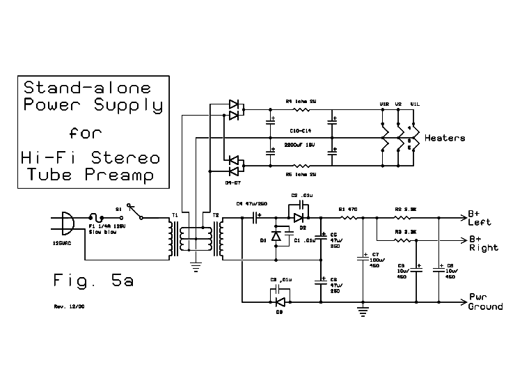
the cathode follower. For a monaural circuit, the simple power supply detailed as part of the
Standalone phono preamp and reproduced below should be entirely adequate.
(Click on image to view a larger version of the schematic.) T1 and T2 are both 12 volt, 0.5 ampere
units. For stereo use (two units) however, the increased demand would probably cause the B+ to sag
excessively. One workaround would be to use a 12 volt, 1 ampere transformer for T1, a 9 volt, 0.5
ampere transformer for T2, and doubling all B+ supply filter capacitor values.


