"Spunky"
by Fred Nachbaur, Dogstar Music ©2001
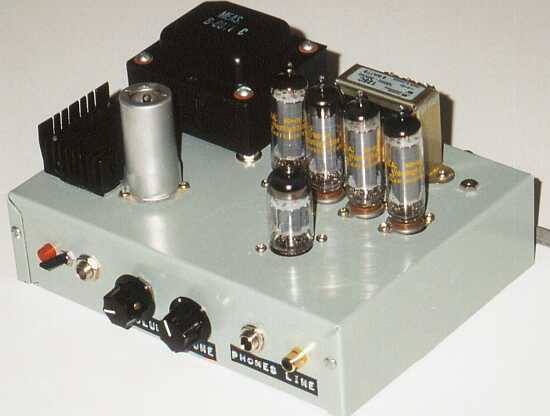
The completed "Spunky" chassis
3: Construction
COMPONENT SELECTION OPTIONS
A: Tubes (valves)
This project was designed with the 35C5 in mind for the four output tubes. It's still readily
available, and for this particular project the only tube I can recommend as an alternative is
the 30A5/HL94. However, if you use this valve, increase the values of R1 and R2 from 240 ohms
to 300 ohms to account for the lower filament voltage.
By reworking the filament power scheme you might be able to get other output tubes to work.
However, I really don't recommend this unless you've got plenty of experience (in which case
you'd probably prefer to work up your own design anyway!)
Similarly, the driver/phase inverter should be a 12AU7, ECC82, or functionally and electrically
similar devices. There's really nothing to be gained by substituting a higher-mu valve such
as the 12AT7/ECC81.
Finally, I really recommend that you find a 9JW8 for the preamplifier tube. From a filament
power standpoint (and even from a pinout perspective) the slightly more common 9U8 will work.
However, the *U8 family is vastly more microphonic, and if you do use a 9U8 be sure to use a
shock-absorbing socket, and also mount the chassis on rubber shock-mounts. At the risk of
sounding like a broken record, I can once again say that getting the 9JW8 is well worth the
trouble. You'll be amazed at how nice this tube sounds, and probably wouldn't have much
trouble convincing your listeners that you're using a 7199. The 9JW8 is listed as available at
Antique Radio Supply at reasonable cost ($4.50 as of
this writing).
It's a good idea to find a shielded socket and shield for the input tube. Such a shielding
arrangement really isn't necessary or desirable for the 12AU7 driver/phase-splitter, but can
be helpful to reduce hum on the 9JW8 preamp.
B: Power Transformer
The little power transformer you see in the photos was a twin to the one on "Li'l 4x4",
scrounged from an old piece of test equipment. This particular one had a total of seven
windings, which I series-connected as required for the needed output voltages. If the truth be
known, the little unit is being pushed to its limits in this application; however, since
Shaza isn't one to play at maximum overdrive for hours on end, I'm sure it'll be fine.
You might similarly get lucky and find something you can use in your junk box ..er.. I mean
treasure chest. If not, the Hammond
Model 269BX
should work, though it too will be somewhat strained. Another alternative would be the
Model 027053201
(175-0-175v at 140 mA) toroidal power transformer available from
Plitron.
240 VAC operation really isn't recommended unless you arrange for a filament transformer in
addition to a suitable plate transformer as per the previous paragraph. Ideally, if you can
find an 85 volt at 150 mA transformer, you can do away with the R1 and R2 filament dropping
resistors. If you're using 30A5/HL94's, a 75 volt at 150 mA transformer would be ideal.
Otherwise, use a 120V at 150 mA transformer and keep the resistors.
C: Output Transformer
You might get lucky, and find a suitable output transformer either in your archives or at
one of the surplus sites. The requirements are:
- Center-tapped Primary
- Primary impedance in the vicinity of 3k (plate-to-plate)
- Secondary impedance 8 ohms (or to suit your intended speaker)
- Power handling capability of at least 8 watts
You can get a clue of power handling ability from the physical size. Have a look at the pictures
of the "Spunky" to get an idea of the size you're looking for.
Your best bet is to duplicate the original design and use the Hammond Model 125C. It has
multiple secondary taps, is rated for 8 watts (perfect!), and is an ideal choice for this
project. The price is not out of line, and it's a near-perfect match to the tubes if you use
taps 1 and 5 for your speaker output.
D: Chassis
A metal chassis (aluminum or steel) is recommended for this project. The one you see in the
pictures was modified from an aluminum project box, final size is 8" x 6" x 2"
(about 200 x 150 x 50 mm). Use a layout similar to mine, or work up your own as needed. I
recommend using a bottom plate for shielding purposes. Similarly, a shielded socket is recommended
for the instrument preamp stage; shielding for the other tubes is optional but certainly not
imperative.
E: Speaker
An efficient speaker or speaker system is important for this project. I was fortunate enough to
have access to several different 8" (200 mm) speakers, and a sound pressure level meter with
which to compare them. The results could be an entire study in itself; suffice it to say that the
most efficient speakers of the ones I tested were relatively inexpensive units intended for
ceiling-mounted public address systems. These have a modestly sized ceramic magnet, quite a
stiff cone assembly (no foam mount), and sport a little whizzer cone. I was particularly
surprised at how poorly a "hi-fi" speaker with a massive magnet fared in this
department; it was fully 4 dB down from the much cheaper PA speakers at the same drive level.
Second best was an old Alnico speaker from a console stereo unit. It was "only" 2 dB
down in response, compared to the PA speaker.
The one I settled on finally was actually one that I already owned, and a twin to the one I
used for "Li'l 4x4". It is (was?) distributed by "Burtek Speakers, Inc., Vancouver
BC": Model No. S81010C, 8", 25W, 10 ozs. magnet, Frequency Res. 80-18000 Hz., Made
in Korea. While its power rating might be a bit optimistic, the stated frequency response is
quite close to what the unit actually handles.
F: Enclosure:
The enclosure you see in the pictures measures 17" x 11" x 8.5" (42.5 x 27.5
x 21 cm.), somewhat larger than the "Li'l 4x4" to accomodate the fact that this unit
dissipates almost twice the amount of heat. The amplifier is housed in the top portion, with an
open back for improved air flow. As in the case of 4x4, it was made from 3/4" solid
hemlock boards, glued together using good-grade wood glue, with small nails to hold it
together while the glue cured. The back panel covering the speaker portion is affixed using
screws. The cutout in the front was carefully made to be a snug fit to the chassis, and a
wooden slat holds the chassis from the rear.
The back panel has a 2" round hole cut into it, near the top and bottom, to provide
pressure-relief ports for the speaker. The unit was painted first with a primer coat of latex
floor paint, then two coats of "speckle" paint, then finished with clear-coat.
Use this same kind of layout if you wish (cute little box, wouldn't you say?), or create
your own lovely little amp to taste.
The logo plate was made from a piece of phenolic positive-resist PC board material, exposed and
etched using the artwork available by right-clicking on
this link and saving spunklog.gif to disk. Print it out at 300 dpi
(final size = 4.5" x 1.5"). Here is a reduced-size version of the image, to give you
an idea of how it looks:

Photocopy it onto clear mylar intended for the purpose, and use it to expose your pc board. Etch
and clean as usual, then coat the resulting copper image with solder. I let the solder "pool"
on the main part of the logo, giving a neat 3-D effect; on the "by Dogstar Music"
portion I used solder-wick to pick up the solder for a flat 2-D effect. The final result was
sprayed with clear-coat and affixed to the case with small screws.
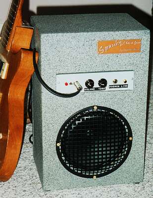
The Final Result
GENERAL CONSTRUCTION HINTS
Wire the filament supply first. I highly recommend that you use a three-prong power cable, with
the ground (green wire) connected to chassis. Note that the 9JW8 preamp is connected to the
neutral side of the power cable (white wire). This is important to minimise hum from
the raw AC power line through the filament wiring. Route the filament wiring away from the rest
of the circuitry as best possible.
Then wire all the grounds, using a "star grounding" approach. All subsystems are
grounded to a central tie point, with the only connections to chassis being the input jacks. Care
with grounds is the biggest single thing you can do to insure that your final result is free of
hum. The idea is to prevent any AC current-carrying lines from sharing the same return run with
the signal path. Within a given stage, you use the center-post on the tube socket as a local
ground for signal only; don't share the same local ground with power supplies.
Where possible, I mounted parts directly to the tube sockets. The rest of the components were
mounted on perf-board subassemblies. This is a nice way to build, it's more space-efficient than
the conventional terminal-strip approach. The rectifiers and filter capacitors for the B+ and
bias supplies were similarly assembled on perfboard, which was mounted to the chassis using
standoffs.
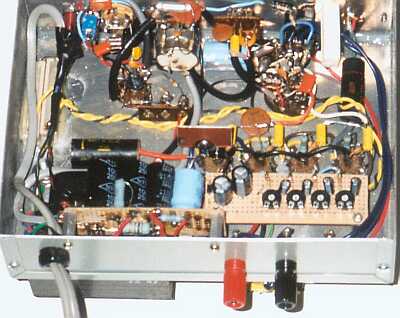
"Spunky's" inner workings
Route power wiring away from signal wiring wherever possible. Be especially careful about the
line-operated filament lines to the output tubes, both for noise and safety considerations. Try to
keep lines as short and "to the point" as possible. Use shielded wire for signal lines,
especially to the input jacks, volume and tone controls, and between stages. Ground only one end of the
shielded cable runs.
It should be noted that the line "input" also operates as a "line out" from
the instrument preamp, for recording purposes or what-have-you. You can similarly use the line
input simulateously with the guitar input, e.g. drum machine or synth backup.
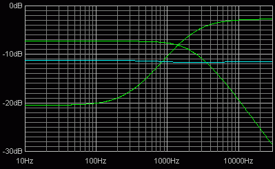
The tone stack was designed using Duncan Monroe's "Tone Stack Calculator," available
from his site at
http://www.duncanamps.com. The values shown result in a
set of curves approximately as shown below. The cyan line represents response at the middle of
the control setting, and the green lines at the end extremes.
There is plenty of room for experimentation with this little design. One of the nice things is that
the components are inexpensive and quite forgiving; as such, this is an ideal project for
learning lots about tubes and sound in general, without the constant fear of blowing up something
rare and expensive. But please - do be careful. Even expensive parts can be replaced; you can't.
SETTING BIAS
The bias controls independantly set the "operating point" of the output
tubes, in other words how much current they draw under no-signal
conditions. The little 10 ohm resistors at each cathode (pin 1) are
convenient metering points. Optimum bias will depend on your supply voltage, as well
as your sonic preferences. Higher plate (and therefore cathode) current results in a
fatter sound and a bit more power, whereas lower current gives a more restrained sound,
and also is easier on your output tubes.
The maximum combined plate and screen dissipation for the 35C5 is given as 6.3 watts. You
can derive the approximate cathode current corresponding to this maximum by dividing
6.3 by your supply voltage. Assuming that it's around 165 volts (as is my prototype), this
comes to about 38 milliamperes. I personally wouldn't go any higher than about 30 mA,
preferring about 25 mA. per tube.
Adjust each tube's bias pot while measuring the voltage at the corresponding pin 1.
The idea is to set them all the same; you might have to go around a couple times, since
changing the adjustments has a minor effect on the other ones also. To maximize tube life
while retaining the sound you prefer, gradually decrease the bias current (voltage across
the metering resistors) until you hear a "thinning out" of the sound, then back
it up a little again.


