April 30, 2002
Tech article
Part 1: Filament and Control Supplies
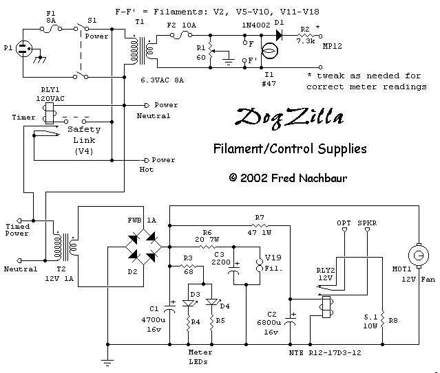
Before we have an amplifier, we need a power supply. So we'll start with the basics, the filament
and control supplies shown below.
AC power is supplied via AC Fuse F1 and Power On/Off switch S1 to 6.3V
filament transformer T1. Fuse F2 is provided as an additional safety feature,
since a short to the filament transformer may not be enough to blow the main power fuse.
Hum balance pot R1 is provided for good measure, though it's unlikely to have much
of an effect given the overall design of the amplifier. This supplies filament power to
most of the tubes in the unit, as well as the #47 pilot light I1.
Note that T1 does not provide filament power for tubes V1,
V3, V4 and V18. V4 is a gas regulator tube, and obviously
doesn't need filament voltage. V1 and V3 are in the high-voltage regulator
circuitry, and require isolated filament supplies because their cathodes are sitting at
high voltage above ground; these will be covered in the
HT section. V18, the first gain-stage input pentode, is
treated specially to a DC supply (covered in the below)
to reduce the possibility of filament-induced hum.
D1 and R2 provide rectification and current limiting for metering the
supply voltage. Note that in all schematics, "MP" represents a metering point;
the metering circuit is further detailed in next section.

Schematic, Filament and Control Supplies
Switched AC voltage is also applied to a timer relay RLY1. I used a commercial
timer block for a standard octal relay, by Releco; this is rather pricey, however, and
DIY timer circuits are readily available if you search the web. This timer delays for a
variable time (on the order of 20 seconds) to allow all the important filaments to reach
full temperature before energizing the main HT supply. The input to the timer relay is
also routed through the "safety link" incorporated in gas regulator V4
(pins 3 and 7), preventing energizing of the HT supply (and very probable damage) if the
unit is powered up with the regulator removed.
This timed AC is also applied to 12-volt control transformer T2, the output of which is
rectified by full-wave bridge rectifier D2, and filtered by capacitor C1. This
DC voltage powers red and blue LED arrays D3 and D4 built into the meter
housing; it's quite the effect when the HT circuit kicks in, and the meter lights up.
Dropping resistor R3, in conjunction with R4 and R5 (chosen as
appropriate for the LED arrays) limit the current through the LEDs to a safe value.
This DC voltage is further filtered and dropped to 6.3 volts by the network consisting of
R6 and C3, providing filament power for the 6K7 input pentode V18.
The DC voltage is also applied to a small 12V relay, RLY2 via R7 and
C2. Its contacts are in series with the main speaker output line. This causes a
slight (about 1/2 second) delay after energizing the HT supply, avoiding the pop or snap
that could otherwise result as the amplifier stabilizes. During the time it takes the
relay to engage, the contacts connect to a small dummy-load resistor to prevent transients
from being reflected back to the output tubes.
Finally, the DC voltage is used to energize a small DC fan, MOT1 which helps to
keep the components under the chassis cool. The top-side components (tubes and
transformers) will generally get enough cooling by convection, but the underside
components can use some help. A small fan is cheap insurance in this respect.


