
April 30, 2002
Part 5: PA Driver
The driver circuit consists of a garden-variety preamplifier stage, followed by a "cathodyne"
phase splitter (also known as a "concertina" phase splitter, because the plate and cathode
voltages travel in opposite directions, much like the ends of the little accordion for which it's
named).
Preamplifier:
There's not much to be said about this stage, which simply provides voltage gain, giving full
output with an input of about 3 volts RMS. R63 and C26 decouple the plate supply,
R75 is the plate load, and R65 provides cathode biasing. The cathode bias resistor
is bypassed by C27 for maximum gain. R66 is the grid resistor, and
C24 couples the output to the cathodyne phase splitter. C26 puts a 3 dB
corner at about 15 kHz to limit frequency response... and that's about all there
is to it.
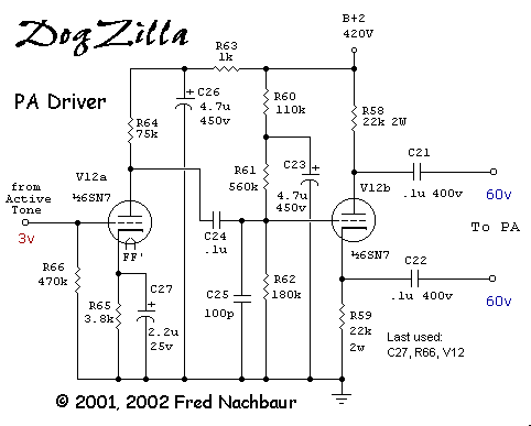
Schematic, PA Driver and Phase Splitter
Phase Splitter:
The cathodyne phase splitter is perhaps the most common method for supplying equal-but-opposite
signals to push-pull output stages. Its simplicity makes it very popular, but that same simplicity
can also be deceptive. For instance, if the loads to the two outputs are identical, it can easily
be proven that the output voltage will be the same. (Hint: since the grid draws no current, the
currents through the plate and cathode resistors will be equal. Since the resistances are equal,
it follows that the voltage drops will be equal. This is true both from a DC perspective, as well
as an AC standpoint. The only difference is that in the AC equivalent circuit, the load resistances
are effectively in parallel with the plate and cathode resistors.)
However, if the plate and cathode loads are different, the rule about equal voltages falls apart.
This is why a cathodyne is not appropriate for directly driving stages that draw grid current during
part or all of the cycle, and is one reason why DogZilla sports voltage followers before the finals.
This is a good opportunity to actually step through the procedure of designing a cathodyne phase
splitter. Others may have different approaches, and by no means do I proscribe the following method
as "the one true way." However, it works for me, and therefore might be useful for others
also. It's rather intermediate between the rigorous textbook approach, and the more common
"seat of the pants" approach used by most hobbyists. If you want to skip this
mini-tutorial, click here.
First we get the plate curves for the triode we intend to use -- in this case the time-proven
workhorse 6SN7. (The popular 6FQ7/6CG7 will be very similar). We'll also keep in mind the maximum
power dissipation, given as 5 watts for either section, or 7.5 watts total for both. To be safe,
let's say a maximum of 3.75 watts. The other important design spec is the required output voltage
swing. For the 807, in Class AB2 operation, this will be 96 volts P-P (from the spec
sheet), which typically would allow for positive grid swings up to +13 volts (assuming a bias
point of -35 volts). If you're restricting your amplifier to Class A or Class AB1
(i.e. grid never goes positive), you can approximate your maximum output swing as twice the
DC grid-bias value.
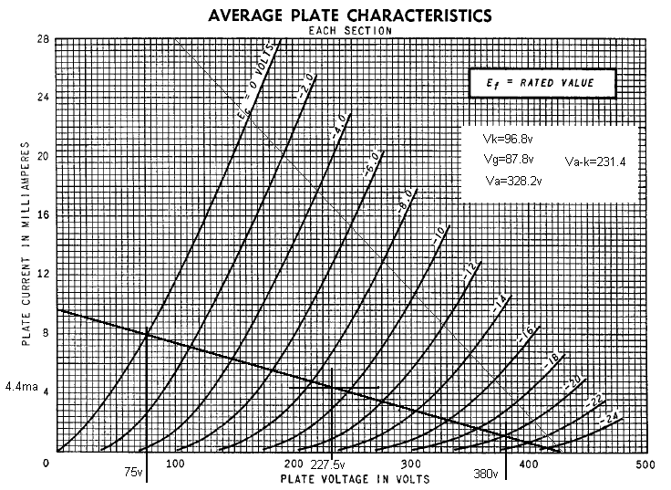
Cathodyne Phase Splitter Design
In the case of DogZilla, we have quite an array of possible supply voltages to choose from; we
could even get fancy and use split (positive and negative) supplies. However, let's start simple and
postulate that we'll be running from the +420 volt supply. That gives us the first point on our
load-line, so we place a point at 420 volts on the X (plate voltage) axis. This represents the
plate-to-cathode voltage if the tube were completely cut-off (zero plate current).
Next we do a bit of playing around. Most cathodyne circuits, in order to provide the maximum output
swing, will be biased with the plate-to-cathode voltage at a little over 1/2 the supply voltage.
In our case, this would be on the order of 210-250 volts. Let's say 250 volts as a starting point.
Given our maximum power dissipation limit of 3.75 watts, this would mean a quiescent plate current
of (3.75/250) = 15 mA. We can draw a tentative line through this point (250V, 15 mA) from the
Vp = 420 reference point. This line (shown as a thin line on the graph) represents our
maximum (steepest) load line, with the tube "grunting" full-out.
Note that the distance between adjacent grid lines is not constant along the load line. They get
scrunched together more and more at the cutoff end (right side of the graph). This represents
non-linearity, which is the fundamental cause of harmonic distortion. If you're so inclined, draw
a few more load lines (or just use a straight-edge to eyeball them). You'll find that linearity
gets worse with very shallow load lines. While such load lines will be very kind to your tubes,
they also won't necessarily give you acceptable sound. However, there will generally be quite a
wide range of load-line slopes over which linearity does not change significantly.
The thick load-line in the graph represents the value I settled on for DogZilla. If you went to the
trouble of plotting the linearity, you'd find that the linearity curve is somewhat different
from the "full-out" curve, but not particularly worse. This represents a quiescent
power dissipation on the order of 1 watt, a level that is definitely "6SN7 friendly."
Having settled on a load-line, let's determine the plate and cathode resistor values. The point where
the load-line intercepts the Y axis represents the current that would flow if the tube were
short-circuited. In the graph above, this would be 9.6 mA. If we divide this into the supply voltage,
it will give our total resistance, or (420/9.6) = about 44k. Given that the plate and cathode
resistors must be equal, it follows that both will be 22k in value.
Now, let's determine our maximum range of excursion along the load-line. The left-hand side is easy,
since we have to remain in Class A1 operation, this limit would correspond to the point
where grid voltage equals zero. Draw a vertical line at that point, intercepting the X axis at (75
volts). The right-side point is a bit more rubbery, and depends on how much non-linearity you want
to put up with. The point at which grid volts = 20 looked reasonable to me, draw a line to the
X-axis passing through this point (380 volts). The mid-point of this line segment would therefore
fall at (75+380)/2 = 227.5 volts. Plate current at this point would be about 4.4 mA, dissipation
about 1 watt, as expected.
Next, let's calculate our plate and cathode voltages at the quiescent point. 4.4 mA through 22k
represents a voltage drop of 96.8 volts. So the cathode will be at 96.8 volts, and the plate at
(420-96.8)=323.2 volts. As a cross-check, the plate-to-cathode voltage will be the difference
between the two voltages, or 226.4, agreeing nicely with that point on the graph.
Now, let's look at our actual plate and cathode voltages at the two extremes, to see
if we have enough headroom. We'll also use grid voltage = -9 volts as a reference, to get an idea
of linearity. At grid-cathode volts = 0, plate voltage will be 75 volts. That means that the
balance of the 420 volts will be evenly divided between the plate and cathode resistors, or
(420-75)/2 = 172.5 volts, or (172.5-96.8)=75.7 volts above quiescent. At the other extreme of
grid voltage swing (Vg= -18V), the plate voltage according to the graph will be about
352V. Again, the difference is split between the loads, which means that each load would see
(420-352)/2 = 34 volts, or (96.8-34)=62.8 volts. The total swing would therefore be (75.7+62.8)=
138.5 volts, well in excess of the worst-case 96 volts required by the output stage grids.
You may have noticed that the excursions are not equal in both directions. Each limit is about
10% off from the median value. Also, the midpoint of the grid voltage swing (-10 volts) is close
to, but not identical with the midpoint of plate voltage swing (227.5 volts). This is due to
non-linearity. Since we really don't /need/ a full 138 volts of swing, let's see if we can improve
our linearity by shifting our operating point somewhat to the left. So let's try placing our
quiescent grid voltage at -7 volts, corresponding to a plate voltage of 200V and current of 5.2 mA.
The excursion on each output would therefore be (200-75)/2=62.5 volts leftward, and (300-200)/2=50
volts rightward, or a total of 112.5 volts total excursion, still quite reasonable. However,
contrary to expectations, the deviation from the mean is now 12%! So we haven't gained anything, and
might as well stay with our original figures. (It bears noting at this point that this non-linearity
will be reduced by the mu of the tube in actual practise, due to local negative feedback on the
cathode resistor.)
All that's left now is to define the grid bias. We've found that under quiescent conditions, the
cathode will be sitting at 96.8 volts. The grid will be at -9 volts relative to the cathode, or
87.8 volts. This can be used to calculate the divider network on the grid. If you calculate it out,
you'll find that with the resistor values given, the actual value comes out to 89 volts, certainly
close enough. Note that the top resistor is broken into two sections, with capacitor C23
decoupling the circuit for AC. The effective input impedance to the stage is therefore R62
and R61 in parallel, or 136k.
As a final note, it bears pointing out that the voltage divider grid bias scheme (as shown here)
is an excellent alternative to the usual approach of referencing the grid to a tapped cathode
resistor. The present approach is especially useful if the supply voltage is regulated, and will
be extremely stable with changes in the tube's characteristics as it ages. The tapped cathode
resistor approach will generally be more useful if the supply voltage can be expected to vary, as
it will tend to offset such changes; however, it's more prone to drift in operating point with
tube aging.


