| BAMTRAT SCHEMATICS |
|
Click on the text links or on the thumbnail images to view a full-size version of
each schematic section. If you click on the thumbnail, it will spawn a new window,
so that you can easily refer to the schematics while referring back the descriptions.
(Clicking on the text links re-uses your current window.) Let me know if you
have difficulties with this. You can also right-click/ Save As... on any of the links
to download the files for local viewing. A section-by-section walkthrough is also available. |
| Schematic 1: | Original Battery Tube Radio Schematic |

|
This is the schematic of the original Viking radio before I completely tore it down to refurbish the chassis. All the major components were reused in the rebuild into a theremin, the exception being the carbon resistors, wax/paper capacitors, and the old cloth-covered wiring. Note that the 365 pF antenna tuning section is associated with the 230µH coil, and the 185 pF oscillator section is paired with the 136µH coil, for the required tracking to a constant IF. |
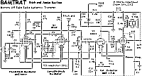
| Schematic 2: | Pitch and VCA Section |

|
Here are the pitch oscillators, voltage-controlled amp (VCA), and power amp. This is essentially a rewire of the original schematic, using all the major components of the original radio. Note that the tuning capacitor sections are reversed to their respective coils, plus the added Ct tank capacitor, causing frequency tracking to overlap. You could make a pitch-only theremin from this schematic alone, by removing R9, R10 and C10, and tying R8 to ground instead of +3V. |
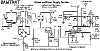
| Schematic 3: | Power Supply and Volume Section |

|
These are the sections added to make a complete theremin, including an AC Power supply (Battery Eliminator). I used my "Back-to-back Wall-Wart"(™) approach to derive the 3v filament, 7.5v C-, and 80v B+ voltages, while maintaining line isolation. Note the new series-parallel filament arrangement, which halves the required current from the power supply. Also included is the added volume oscillator, which relies on one of the old IF transformers (with an added winding) for oscillation and slope-detection for the VCA. |
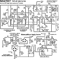
| Schematic 4: | Full schematic |

|
If you prefer to view the entire schematic in a single sheet, download this
version.
The Technical Details section of this site breaks this schematic down into its component sections, with a brief description of each. |
|
MORE ABOUT "BAMTRAT"
Description and Pictures Technical details Sound Samples |
Back to my Theremin Index page
Back to Fred's Vacuum Tube Projects
To my music home page
Email me