
Technical Description
|
General Notes:
This page steps through each section of my implementation of BAMTRAT. Many of the component values shown were determined experimentally, to suit my own tastes and preferences. As when building an acoustic instrument, there is a lot of room for experimentation and customisation in electronic instruments generally, and theremins specifically. A note on capacitors: here's an opportunity to use ceramic capacitors, especially the NPO variety. While ceramic caps are generally considered less than ideal for hi-fi audio, they're terrific for RF; they tend to have less capacitance drift with temperature than most plastic types, and also have a vanishingly small "equivalent series inductance" as compared to capacitors wound with foil and film. Following are each individual section of the final BAMTRAT design, with accompanying technical descriptions. |
| Power Supply |
|
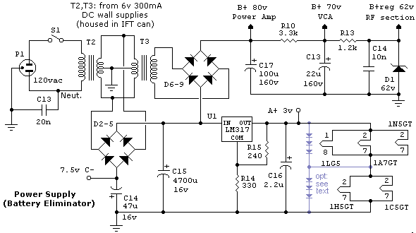
This simple-yet-effective "Battery Eliminator" provides the required
voltages (+80, +3 regulated and -7.5) to operate BAMTRAT. It uses two transformers
salvaged from 6v, 0.3A "wall-wart" supplies to step the voltage down for
the filament and C- supplies, and back up to supply the B+ voltage.
The 6v AC output is follwave-rectified by the positive side of bridge D2-5, filtered by C15, and regulated by an adjustable regulator (LM317), providing regulated 3v for the series-parallel connected tube heaters. It's a Really Good Idea to include six 1N4002 diodes as shown in blue, as protection in case one or more of the tubes are removed from their sockets; this will prevent voltage from ever exceeding about 1.8 volts. The negative side of the bridge supplies the negative bias voltage for the power amp, filtered by C14. Since there's very little current drawn from this supply, even the 47µF shown is an overkill. The stepped-up B voltage is rectified by bridge D6-9, and two-stage filtered by C17, C13 and R10. Since the PA draws the most current and isn't critical as regards ripple, its supply is taken from the first filter section. The voltage-critical RF oscillators are powered by a simple regulator consisting of R13 and zener diode D1. It bears noting that this circuit relies on the self-limiting nature of the specified wall-supply transformers to give the proper B+ voltage. If you use an alternate approach, you'll have to insure that the raw B+ voltage does not exceed about 90 volts under a 20 mA. load. Note also that voltage can briefly soar up to about 160 volts while the tubes are warming up; for this reason, don't skimp on the filter capacitor voltage ratings. An undocumented refinement is the addition of small (I used 3000 pF) capacitors across each of the eight rectifier diodes. This can help solve a 60 Hz modulation that sometimes plagues RF circuits. The best explanation of this that I've seen is on this page by North Country Radio. |
| Audio Power Amplifier |
|
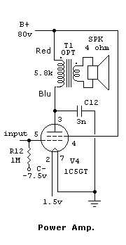
This extremely simple power amplifier section is almost identical to the
original radio. The difference is the use of a lower-value grid leak
(helps reduce hum and spurious RF pickup), and biasing the grid to a
fixed C- supply instead of deriving its bias from a dropping resistor in
the B+ line.
Although the maximum output is a mere 1/4 watt, the sound level is quite surprising; my trusty SPL meter measured up to 84 dBm. As in the original, C12 limits high-frequency response to "mellow" the sound and reduce the possibility of instability. You may wish to also put a small capacitor (e.g. 200 pF) from the control grid to ground to further mellow the sound, should you find the "RCA sound" not to your liking. |
| Voltage-controlled Voltage Amplifier |
|
Again basing the circuitry on the original voltage amplifier in the radio, this
stage amplifies the incoming signal, applied via the manual master volume control
pot and coupling cap C9 to the control grid of triode V3. As before, a 1 meg plate
load resistor and capacitor C11 couples the output to the PA stage.
However, the grid is DC biased to a positive (+3v) rail via a large grid-leak. At the same time, a negative voltage derived from the volume slope detector coil, rectified by the diode section of V3, is applied via a low-pass filter and summing network consisting of R8, R9 and C10. The volume oscillator is set up such that it is normally at or near resonance, resulting in a large negative voltage, and reducing the gain to minimum. As the slope-detector is detuned by moving your hand closer to the volume antenna, this negative voltage decreases, allowing stage gain to increase. |
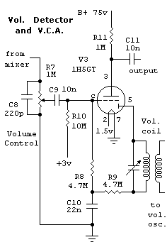
An alternate approach is to use a 1N34 germanium diode instead of the built-in vacuum diode, with the anode to ground, and R10 tied to C- (- 7.5v) instead of to +3v. Tune the slope detector such that resonance is achieved very near to the volume antenna. This may give better control, but at the expense of having the volume drop very suddenly if you get too close to, or in contact with the volume antenna. |
| Variable Pitch Oscillator |
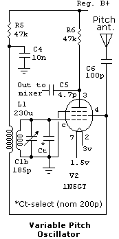
The former IF amplifier pentode, V2, is called into service as our variable pitch oscillator (controlled by the player via the pitch antenna). It's a pretty standard Armstrong oscillator topology, using the original antenna coil as the tank, and the original oscillator section of the tuning capacitor in parallel with an experimentally selected padding cap Ct. |
By swapping the oscillator and antenna coil and capacitor sections, the
frequencies of the two pitch oscillators still track, but no longer at
the same rate. Ct is chosen such that the frequency curves actually
cross near the low end of the tuning dial. This allows for accurate
control using a single adjustment. However, it should be noted that the
frequency of operation is within the AM broadcast band; if you live in a
heavily populated area, you'll have to pad both oscillators to push the
"crossing" frequency below 550 kHz.
The use of the antenna winding of the original antenna coil as our feedback winding has two interesting "side effects." Because of its relatively large inductance and close coupling to the tuned coil, it produces a signal with a large harmonic content; exactly what Lev Termen did to get that unique sound! Secondly, since the original coil was designed to be approximately self-resonant with the radio's antenna, it adds a second set of poles to the circuit. As a result, connecting the pitch antenna to the feedback coil gives a much greater sensitivity than if it were connected to the grid side! |
| Fixed Pitch Oscillator and Mixer |
|
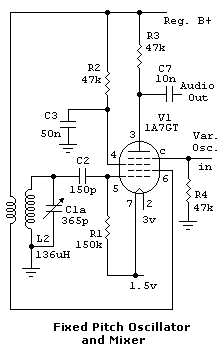
Except for the coil/capacitor swap, the fixed pitch oscillator is virtually
identical to the original local oscillator circuit in the AM radio.
Unlike an AM radio, however, the mixed frequency product is not an
intermediate RF frequency; rather, it's our raw audio signal.
Note the relatively low resistance at the mixer grid input (47k). Combined with the low value of coupling capacitor C5 (4.7 pF) this helps give enough independance between the two oscillators, while still providing enough cross- coupling to cause the oscillators to lock near zero-beat, making frequency adjustment less critical. |
|
| Volume Oscillator |
|
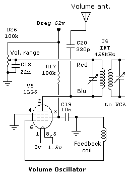
The added volume oscillator, again using the Armstrong topology, employs one of the
IF transformers from the radio. A separate winding was added for feedback; this is
not very critical, I found that I could carefully pull one of the coil bobbins from
the other IFT, and removed about half of its turns from the inside. It could then
easily be slipped over the end of the "good" IFT, adjacent to the coil
furthest from the adjustment capacitor.
Adjustment R26 controls the plate voltage, and therefore the intensity of oscillation. This gives additional control over the volume adjustment range, and essentially just needs to be set once. As an afterthought, I also added a 10 pF panel-mounted trimmer capacitor in parallel with the output coil, as an aid to fine adjustment of volume responsiveness. |
|
MORE ABOUT "BAMTRAT"
Description and Pictures Full Schematics Sound Samples |
Back to my Theremin Index page
Back to Fred's Vacuum Tube Projects
To my music home page
Email me